background image

 3–22

Configuring Your DeviceNet Adapter Offline

Publication 17946.5.5 - October 1996

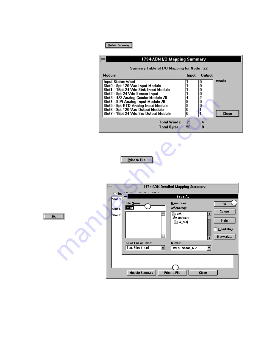
A complete module summary can be viewed by clicking on the

 button. 

This summary shows each slot, configured 

module, input words used, and output

words used. Input and output words are

totaled.

The total words indicated are used in configuring the scan list table
in your 1771-SDN scanner module.

Use the 

 button to print the I/O detailed mapping

summary to a text file. The text file will include both input and
output mapping. A sample text file is shown below.

1. Click on the print to file" button to

pull up the save as" screen.

2. Type in a name for the text file.

3. Click on                          to save the file.

2

1

3

Summary of Contents for Series B

Page 1: ...User Manual DeviceNet Adapter Module Cat No 1794 ADN Series B Allen Bradley ...

Page 2: ...ts such as those described in this publication Reproduction of the contents of this copyrighted publication in whole or in part without written permission of Allen Bradley Company Inc is prohibited Throughout this manual we make notes to alert you to possible injury to people or damage to equipment under specific circumstances ATTENTION Identifies information about practices or circumstances that ...

Page 3: ...creens for ease of movement between screens The Set to Defaults button has been changed to Set to I O Only This applies the real time values for I O optimal settings to the module A Memory button has been added to the individual configuration screen for each module If you change your mind about any settings you have made while you are on the configuration screen clicking on the Memory button retur...

Page 4: ...es 1 1 EMC Directive 1 1 Low Voltage Directive 1 1 The FLEX I O System 1 2 DeviceNet Adapter Components 1 2 Diagnostic Indicators 1 3 Power Requirements 1 3 Mounting the DeviceNet Adapter 1 3 Mounting on the DIN Rail 1 3 Mounting on a Wall or Panel 1 4 Setting the Network Address Switch 1 6 Wiring 1 7 Chapter Summary 1 8 How Communication Takes Place and I O Image Table Mapping 2 1 Chapter Objecti...

Page 5: ...ut Module 2 8 8 point Discrete Input Module 1794 IA8 Image Table Mapping 2 9 Memory Map of 8 point Discrete Input Module Image Table 1794 IA8 2 9 Input Delay Times for the 1794 IA8 Input Module 2 9 8 point Discrete Output Module 1794 OA8 Image Table Mapping 2 10 Memory Map of 8 point Discrete Output Module Image Table 1794 OA8 2 10 8 point Discrete Relay Output Module 1794 OW8 Image Table Mapping ...

Page 6: ...1203 FM 2 27 Defaults 2 28 Configuring Your DeviceNet Adapter Offline 3 1 Chapter Objectives 3 1 About DeviceNet Manager 3 1 Adding Your Flex I O DeviceNet Adapter to the Network 3 1 Configuring Your Flex I O Adapter and System Offline 3 3 Configuring Your Adapter s Flex I O System 3 5 Configure Slot 0 3 6 Configure Slot 1 3 7 Configure Slot 2 3 8 Configure Slot 3 3 9 Configure Slot 4 3 10 Configu...

Page 7: ...em 4 8 Configure Slot 0 4 9 Configure Slot 1 and 2 4 10 Configure Slot 3 4 10 Configure Slot 4 4 11 Configure Slots 5 and 6 4 11 Configure Slot 7 4 12 Applying Configuration Information to the Adapter 4 13 Viewing the Mapping Summaries 4 14 Using Mini Who and Network Who 4 16 Using Mini Who 4 16 Using Network Who 4 17 Troubleshooting 5 1 Chapter Objectives 5 1 Troubleshooting With the Indicators 5...

Page 8: ...r the programmable controller as the controller or the processor The contents of this manual are as follows Chapter Title What s Covered 1 Overview of Flex I O and Your DeviceNet Adapter Describes features capabilities and hardware components 2 How Communication Takes Place and I O Mapping Describes communication over the I O backplane between the modules and the adapter and how data is mapped int...

Page 9: ...utomation Wiring and Grounding Guidelines 1770 4 1 Flex I O Product Data 1794 2 1 16 Source Output Module Cat No 1794 OB16 1794 5 3 16 Sink Input Module Cat No 1794 IB16 1794 5 4 4 Output Analog Module Cat No 1794 OE4 1794 5 5 8 Input Analog Module Cat No 1794 IE8 1794 5 6 8 Sensor Input Module Cat No 1794 IB8S 1794 5 7 8 Input Module Cat No 1794 IA8 1794 5 9 8 Output Module Cat No 1794 OA8 1794 5...

Page 10: ...ds in whole or in part documented in a technical construction file EN 50081 2EMC Generic Emission Standard Part 2 Industrial Environment EN 50082 2EMC Generic Immunity Standard Part 2 Industrial Environment This product is intended for use in an industrial environment Low Voltage Directive This product is tested to meet Council Directive 73 23 EEC Low Voltage by applying the safety requirements of...

Page 11: ...ate wiring for two or three wire devices I O module contains the bus interface and circuitry needed to perform specific functions related to your application For information on how communication occurs on the Flex I O system backplane refer to Chapter 2 The adapter module consists of the following major components diagnostic indicators DeviceNet wiring connections 24V dc power wiring connections N...

Page 12: ...rrent of 400mA at 24V dc from an external power supply for Flex bus operation This is sufficient to support one logical rack 8 modules Remember to add this amount to current requirements for other modules using the same 24V supply The DeviceNet adapter module can be DIN rail or wall panel mounted Refer to the specific method of mounting below Mounting on the DIN Rail B C A 1 Position the adapter m...

Page 13: ...ertain that the DIN rail is properly grounded to the panel Refer to Industrial Automation Wiring and Grounding Guidelines publication 1770 4 1 Mounting on a Wall or Panel To mount the remote I O adapter module on a wall or panel you must have the 1794 NM1 mounting kit The kit contains a special plate and screws necessary for wall panel mounting Proceed as follows Install the mounting plate on a wa...

Page 14: ...eviceNet Adapter Module Mounting Screws 18 2 for the mounting plate and 2 each for the 8 possible modules 4 Hold the adapter 2 at an angle and engage the top of the mounting plate in the indention on the rear of the adapter module 5 Press the module down flush with the panel until the locking lever locks 6 Position the termination base unit up against the adapter and push the female bus connector ...

Page 15: ...itch Valid settings range from 00 to 63 Press either the or buttons to change the number Network Address Switches Note The baud rate for the adapter is set by way of baud detection at power up The setting of the network address cannot be changed using the DeviceNet configuration software DeviceNet Manager Setting the Network Address Switch ...

Page 16: ... High RED Wire V CAN Controller Area Network NOTE Cable colors are shown on the wiring label on the front of the module 2 Insert connector into mating connector on DeviceNet adapter module 3 Connect 24V dc input to the left side of the lower connector E 4 Connect 24V common to the left side of the upper connector D 5 Connections G and F are used to pass 24V dc power G and 24V common F to the next ...

Page 17: ...r Module Publication 1794 6 5 5 October 1996 In this chapter you learned about the FLEX I O system how to install your DeviceNet adapter module and set your switches Chapter 2 tells you how to communicate with your system Chapter Summary ...

Page 18: ...apter communicates with its I O modules over the backplane Inputs Status Outputs Configuration Slot 0 I O Module Read Words Write Words 0 15 Read Write DeviceNet Adapter Inputs Status Outputs Configuration Slot 1 I O Module Inputs Status Outputs Configuration Slot 7 I O Module Network The I O map for a module is divided into read words and write words Read words consist of input and status words a...

Page 19: ...modules The Output data for Slot 0 is received first followed by the Output data for Slot 1 and so on up to slot 7 The first word of input data sent by the adapter is the Adapter Status Word This is followed by the input data from each slot in the order of the installed I O modules The Input data from Slot 0 is first after the status word followed by Input data from Slot 2 and so on up to slot 7 A...

Page 20: ...t 3 This bit is set 1 when an error is detected in slot position 3 I O Module Fault 4 This bit is set 1 when an error is detected in slot position 4 5 This bit is set 1 when an error is detected in slot position 5 6 This bit is set 1 when an error is detected in slot position 6 7 This bit is set 1 when an error is detected in slot position 7 Node Address Changed 8 This bit is set 1 when the node a...

Page 21: ... unacknowledged depending on the run time configuration of the system Cyclic data is sent cyclically by the adapter based on a configured time value Data is independently received cyclically from the sender Data in both directions can be acknowledged or unacknowledged depending on the run time configuration of the system All Flex I O modules are supported by the DeviceNet adapter At present these ...

Page 22: ... Size D15 D14 D13 D12 D11 D10 D9 D8 D7 D6 D5 D4 D3 D2 D1 D0 Read Word 1 Not used Read Word 2 Not used DT 12 15 DT 00 11 Write Word 1 Where D Input Data D0 corresponds to input 0 D1 corresponds to input 1 etc DT Input Delay Time DT 00 11 corresponds to inputs 0 thru 11 DT 12 15 corresponds to inputs 12 thru 15 Input Delay Times for the 1794 IB16 Input Module Bits Description 02 01 00 Delay Time for...

Page 23: ...10 O9 O8 O7 O6 O5 O4 O3 O2 O1 O0 Write Word 1 Not used Write Word 2 Where O Output value O0 corresponds to output 0 O1 corresponds to output 1 etc 16 point Discrete Input Output Module Image Table Mapping 1794 IB10XOB6 Input Size Output Size 0 to 1 Word 0 to 2 Words Module Image Inputs I O Image Not used Outputs Not used Read Write Not used Memory Map of 16 Point Discrete Input Output Module Image...

Page 24: ...screte Electronically Fused Output Module Image Table 1794 OB8EP Dec Bit 15 14 13 12 11 10 09 08 07 06 05 04 03 02 01 00 Size Oct Bit 17 16 15 14 13 12 11 10 07 06 05 04 03 02 01 00 Size F7 F6 F5 F4 F3 F2 F1 F0 Reserved Read Word 1 Not used FR O7 O6 O5 O4 O3 O2 O1 O0 Write Word 1 Reserved Write Word 2 Where O Output value O0 corresponds to output 0 O1 corresponds to output 1 etc FV overload fault ...

Page 25: ...ic bit for input 2 etc D Input Data where D0 corresponds to input 0 D1 corresponds to input 1 etc DT Input Delay Time where DT 00 11 corresponds to inputs 0 thru 11 DT 12 15 corresponds to inputs 12 thru 15 Make certain that the delay time for 00 11 is the same as the delay time for 12 15 Smart Sensor Bits 08 15 S Diagnostic data 1 Fault present Smart 0 Normal no errors Bits 00 07 D Input data 1 S...

Page 26: ...05 04 03 02 01 00 Size Not used D7 D6 D5 D4 D3 D2 D1 D0 Read Word 1 Not used Read Word 2 Not used DT 00 07 Write Word 1 Where D Input Data where D0 corresponds to input 0 D1 corresponds to input 1 etc DT Input Delay Time where DT 00 07 corresponds to inputs 0 thru 7 Input Delay Times for the 1794 IA8 Input Module Bits Description Maximum Delay Time 02 01 00 Delay Time for Inputs 00 07 Off to On On...

Page 27: ...ite Word 1 Not used Write Word 2 Where O Output value where O0 corresponds to output 0 O1 corresponds to output 1 etc 8 point Discrete Relay Output Module 1794 OW8 Image Table Mapping Module Image Outputs I O Image Not used Not used Not used Input Size Output Size 0 or 1 Word 1 or 2 Words Read Write Memory Map of 8 Point Discrete Relay Output Image Table 1794 OW8 Dec Bit 15 14 13 12 11 10 09 08 07...

Page 28: ...Bit 15 14 13 12 11 10 09 08 07 06 05 04 03 02 01 00 Size Oct Bit 17 16 15 14 13 12 11 10 07 06 05 04 03 02 01 00 Size S Analog Value Channel 0 Read Word 1 S Analog Value Channel 1 Read Word 2 S Analog Value Channel 2 Read Word 3 S Analog Value Channel 3 Read Word 4 S Analog Value Channel 4 Read Word 5 S Analog Value Channel 5 Read Word 6 S Analog Value Channel 6 Read Word 7 S Analog Value Channel ...

Page 29: ... 4 20mA uses all 16 bits Read Word 2 Bits 15 Channel 1 analog data sign bit Read Word 3 Bits 00 14 Channel 2 analog data 12 bit left justified two s complement number unused lower bits are zero 4 20mA uses all 16 bits Read Word 3 Bits 15 Channel 2 analog data sign bit Read Word 4 Bits 00 14 Channel 3 analog data 12 bit left justified two s complement number unused lower bits are zero 4 20mA uses a...

Page 30: ...7 Full range bits F for individual channels Bit 00 corresponds to input channel 0 bit 01 corresponds to input channel 1 and so on Refer to range selection above Write Word 1 Bits 08 15 Configure select bits C for individual channels Bit 08 corresponds to input channel 0 bit 09 corresponds to input channel 1 and so on Refer to range selection above Write Word 2 Bits 00 15 Not used set to 0 Write Wo...

Page 31: ...output 1 and so on ATTENTION These bits must be set to 1 C Configure select bit F Full range bit Range Selection Bits for the 1794 OE4 Analog Output Module Write Word 6 Channel No Channel 0 Channel 1 Channel 2 Channel 3 F0 C0 F1 C1 F2 C2 F3 C3 Decimal Bit 00 08 01 09 02 10 03 11 4 20mA 0 1 0 1 0 1 0 1 0 10V dc 0 20mA 1 0 1 0 1 0 1 0 10 to 10V dc 1 1 1 1 1 1 1 1 Off1 0 0 0 0 0 0 0 0 C Configure sel...

Page 32: ...ts Write Word 4 Bits 15 Channel 3 analog data sign bit Write Word 5 Bits 00 03 Output Enable bits Bit 00 corresponds to input 0 bit 01 corresponds to input 1 bit 02 corresponds to input 2 and bit 03 corresponds to input 3 These bits must be set to 1 Bits 04 15 Not used set to 0 Bits 00 03 Full range bits F for individual channels Bit 00 corresponds to output channel 0 bit 01 corresponds to output ...

Page 33: ...4 03 02 01 00 Size S Analog Value Input Channel 0 Read Word 1 S Analog Value Input Channel 1 Read Word 2 S Analog Value Input Channel 2 Read Word 3 S Analog Value Input Channel 3 Read Word 4 PU Not used set to 0 W1 W0 U3 U2 U1 U0 Read Word 5 S Analog Data Output Channel 0 Write Word 1 S Analog Data Output Channel 1 Write Word 2 Not used set to 0 OE1 OE0 Write Word 3 Not used C5 C4 C3 C2 C1 C0 0 0 ...

Page 34: ...rd 3 Bits 00 14 Channel 2 analog data 12 bit left justified two s complement number unused lower bits are zero 4 20mA uses all 16 bits Read Word 3 Bits 15 Channel 2 analog data sign bit Read Word 4 Bits 00 14 Channel 3 analog data 12 bit left justified two s complement number unused lower bits are zero 4 20mA uses all 16 bits Read Word 4 Bits 15 Channel 3 analog data sign bit Bits 00 03 Underrange...

Page 35: ... to input channel 3 bit 03 corresponds to input channel 3 bit 04 corresponds to output channel 1 and bit 05 corresponds to output channel 2 Refer to range selection above Write Word 4 Bits 06 07 Not used set to 0 Write Word 4 Bits 08 13 Configure select bits C for individual channels Bit 08 corresponds to input channel 0 bit 09 11 corresponds to input channel 1 bit 10 12 corresponds to input chann...

Page 36: ...s Reserved Overrange Calibration Status RTD Type Configuration RTD Analog Input Module 1794 IR8 Read Dec Bit 15 14 13 12 11 10 09 08 07 06 05 04 03 02 01 00 Oct Bit 17 16 15 14 13 12 11 10 07 06 05 04 03 02 01 00 Read Word 1 Reserved Read Word 2 Channel 0 Input Data Read Word 3 Channel 1 Input Data Read Word 4 Channel 2 Input Data Read Word 5 Channel 3 Input Data Read Word 6 Channel 4 Input Data R...

Page 37: ...ead Word 6 00 15 00 17 Channel 4 Input data Read Word 7 00 15 00 17 Channel 5 Input data Read Word 8 00 15 00 17 Channel 6 Input data Read Word 9 00 15 00 17 Channel 7 Input data Read Word 10 00 07 Underrange bits these bits are set if the input signal is below the input channel s minimum range 08 15 10 17 Overrange bits these bits are set if 1 the input signal is above the input channel s maximum...

Page 38: ...odule to compare with the unknown input 03 05 A D Filter First Notch Frequency Bit 05 04 03 Definition 0 0 0 10Hz default 0 0 1 25Hz 0 1 0 50Hz 0 1 1 60Hz 1 0 0 100Hz 1 0 1 250Hz 1 1 0 500Hz 1 1 1 1000hZ 06 Calibration High Low bit This bit is set during gain calibration reset during offset calibration 07 Calibration clock this bit must be set to 1 to prepare for a calibration cycle then reset to ...

Page 39: ... ohm Pt α 0 00385 200 to 630oC 0 1 1 0 Reserved 0 1 1 1 10 ohm Copper 200 to 260oC 1 0 0 0 120 ohm Nickel 60 to 250oC 1 0 0 1 100 ohm Nickel 60 to 250oC 1 0 1 0 200 ohm Nickel 60 to 250oC 1 0 1 1 500 ohm Nickel 60 to 250oC 1 1 0 0 Module data time stamp 1101 to 1111 Reserved 04 07 Channel 1 RTD Type see bits 00 03 08 11 Channel 2 RTD Type see bits 00 03 12 15 Channel 3 RTD Type see bits 00 03 Writ...

Page 40: ...d Overrange Calibration Status Thermocouple Type Configuration Thermocouple Input Module 1794 IT8 Read Dec Bit 15 14 13 12 11 10 09 08 07 06 05 04 03 02 01 00 Octal Bit 17 16 15 14 13 12 11 10 07 06 05 04 03 02 01 00 Read Word 1 Reserved Read Word 2 Channel 0 Input Data Read Word 3 Channel 1 Input Data Read Word 4 Channel 2 Input Data Read Word 5 Channel 3 Input Data Read Word 6 Channel 4 Input Da...

Page 41: ...ord 8 00 15 00 17 Channel 6 Input data Read Word 9 00 15 00 17 Channel 7 Input data Read Word 10 00 07 00 07 Underrange bits these bits are set if the input signal is below the input channel s minimum range 08 15 10 17 Overrange bits these bits are set if 1 the input signal is above the input channel s maximum range or 2 an open detector is detected Read Word 11 00 00 Cold Junction sensor underran...

Page 42: ...ter settles to 100 of a Full Scale step input in 60 scans 03 05 03 05 A D Filter First Notch Frequency Bit 05 04 03 Definition 0 0 0 10Hz default 0 0 1 25Hz 0 1 0 50Hz 0 1 1 60Hz 1 0 0 100Hz 1 0 1 250Hz 1 1 0 500Hz 1 1 1 1000hZ 06 06 Calibration High Low bit This bit is set during gain calibration reset during offset calibration 07 07 Calibration clock this bit must be set to 1 to prepare for a ca...

Page 43: ...15oC 32 to 4199oF 1 0 0 1 N 270 to 1300oC 450 to 2372oF 1 0 1 0 Reserved 1 0 1 1 Reserved 1 1 0 0 Module reports cold junction temperature for channels 00 03 1 1 0 1 Module reports cold junction temperature for channels 04 07 1 1 1 0 Reserved 1 1 1 1 No sensor connected do not scan 04 07 04 07 Channel 1 Thermocouple Type see bits 00 03 08 11 10 13 Channel 2 Thermocouple Type see bits 00 03 12 15 1...

Page 44: ... Reference Channel 2 Memory Map of SCANport Module Image Table 1203 FM Dec Bit 15 14 13 12 11 10 09 08 07 06 05 04 03 02 01 00 Octal Bit 17 16 15 14 13 12 11 10 07 06 05 04 03 02 01 00 Read Word 1 Reserved Read Word 2 Connection Status Channel 2 Connection Status Channel 1 Read Word 3 Logic Status Channel 1 Read Word 4 Analog Feedback Channel 1 Read Word 5 Logic Status Channel 2 Read Word 6 Analog...

Page 45: ...1 4 10 0 1794 IT8 8 pt Thermocouple Input 11 4 10 0 1794 OB8EP 8 pt 24V dc Electrically Fused Source Output 1 1 0 1 1203 FM1 SCANport Module 6 5 6 5 Factory defaults are the values assigned by the adapter when you first power up the system and no previous stored settings have been applied For discrete modules these automatic default sizes are 1 input word 1 output word These values are used for de...

Page 46: ...ing Your DeviceNet Adapter Online For additional information on FLEX I O modules refer to the following publications Module Description Catalog Number For Additional Information Installation User Manual 16 Sink Input Module 1794 IB16 1794 5 4 16 Source Output Module 1794 OB16 1794 5 3 10 Input 6 Output Module 1794 IB10XOB6 1794 5 24 8 Electronically Fused Output Module 1794 OB8EP 1794 5 20 8 Senso...

Page 47: ...User Manual publication 1787 6 5 3 In this chapter we assume that you have established a network and are adding a Flex I O Adapter to your network To add the DeviceNet adapter to the network 1 At the Network Screen click on the add device button 1 2 At the Add Device to Network screen click on communication adapter and then click on the 1794 ADN in the product area 2a 3 Select the device node addr...

Page 48: ...screen 2 2 After adding the adapter to the network you must configure it Return to the network screen You have 2 choices highlight the device and click on the Configure Device button or double click on the highlighted adapter to bring up the adapter configuration screen If a configuration file exists the screen will be populated with the selections in that file The 1794 ADN adapter configuration b...

Page 49: ...nd using the user defined filename or a default name of node address prf 1 2 3 4 5 From the Configuration screen you can To set run fault action for the adapter Reset outputs to zero Hold outputs in last state Use safe state output values set run idle action Reset outputs to zero Hold outputs in last state Use safe state output values set idle fault action Outputs remain in idle Outputs go to faul...

Page 50: ...tion 1794 6 5 5 October 1996 Select your adapter options as shown in the following 1 Select from the list box for each configuration option a run idle b run fault c idle fault d module fault Use the button to show the settings for each option 1a 1b 1c 1 1d ...

Page 51: ...played Use the up dwn arrows to view the entire list of modules 2 Use the up down arrows to page thru the possible module selections Select the desired module by clicking on that selection 1a 1a 1 2 Select the modules you want inserted into each slot in your Flex I O system In the example the following selections were made Example This adapter example has all 8 slots filled with modules 1 Click on...

Page 52: ...emory Changing the amount of output write words causes the adapter to expect more or less output configuration words from the process 1 To specify the number of input and output words place the cursor in the box and backspace to delete Enter the desired selection 4 Click on the OK button to save your edits 3 Set the delay time constant for each set of inputs by clicking on the text box and scrolli...

Page 53: ...sly sent to file Changing the number of input read words generates the amount of input and status area mapped into adapter memory Changing the amount of output write words causes the adapter to expect more or less output configuration words from the process 1 To specify the number of input and output words place the cursor in the box and backspace to delete Enter the desired selection 2 1 3 4 5 2 ...

Page 54: ... input read words generates the amount of input and status area mapped into adapter memory Changing the amount of output write words causes the adapter to expect more or less output configuration words from the process 1 To specify the number of input and output words place the cursor in the box and backspace to delete and then enter the desired selection 5 Click on the OK button to save your edit...

Page 55: ...er to expect more or less output configuration words from the process 6 If you change the settings when all selections are complete click on the OK button 4 If desired enter a value that the module outputs go to in the event of a communication failure if safe state is the action chosen in fault or idle action You can select the radix 4a to use for data entry by clicking on the desired radio button...

Page 56: ...nd status area mapped into adapter memory Changing the amount of output write words causes the adapter to expect more or less output configuration words from the process 1 To specify the number of input and output words place the cursor in the box and backspace to delete Enter the desired selection 5 If you change the settings when all selections are complete click on the OK button 2 3 1 4 5 2a 2 ...

Page 57: ...3a Click on the desired module data type to select 4 Select the desired filter first notch frequency by clicking on the list box A list of frequencies is displayed 4a Select the desired frequency by clicking on that selection 8 This module has an enhanced mode of operation In the enhanced mode inputs are compared against a known precision resistor to determine the value of the RTD Since this is pe...

Page 58: ...ile Changing the number of input read words generates the amount of input and status area mapped into adapter memory Changing the amount of output write words causes the adapter to expect more or less output configuration words from the process 5 If you change the settings when all selections are complete click on the OK button 1 To specify the number of input and output words place the cursor in ...

Page 59: ...amount of input and status area mapped into adapter memory Changing the amount of output write words causes the adapter to expect more or less output configuration words from the process 5 If you change the settings when all selections are complete click on the OK button 1 To specify the number of input and output words place the cursor in the box and backspace to delete Enter the desired selectio...

Page 60: ... Changing the number of input read words generates the amount of input and status area mapped into adapter memory Changing the amount of output write words causes the adapter to expect more or less output configuration words from the process 5 If you change the settings when all selections are complete click on the OK button 1 To specify the number of input and output words place the cursor in the...

Page 61: ...es are the stored sizes previously sent to file Changing the number of input read words generates the amount of input and status area mapped into adapter memory Changing the amount of output write words causes the adapter to expect more or less output configuration words from the process 5 The set to I O only button returns all I O data size settings to the optimal I O settings for this module 1 T...

Page 62: ...d backspace to delete Enter the desired selection 3 Select the module data type by clicking on the list box A list of types is displayed 3a Click on the desired module data type to select 4 Select the desired filter first notch frequency by clicking on the list box A list of frequencies is displayed 4a Select the desired frequency by clicking on that selection 8 This module has a fixed digital fil...

Page 63: ... sizes previously sent to file Changing the number of input read words generates the amount of input and status area mapped into adapter memory Changing the amount of output write words causes the adapter to expect more or less output configuration words from the process 1 To specify the number of input and output words place the cursor in the box and backspace to delete Enter the desired selectio...

Page 64: ...fault mode The default sizes are optimal settings If you do a load from file the sizes are the stored sizes previously sent to file Changing the number of input read words generates the amount of input and status area mapped into adapter memory Changing the amount of output write words causes the adapter to expect more or less output configuration words from the process 5 If you change the setting...

Page 65: ...izes are optimal settings If you do a load from file the sizes are the stored sizes previously sent to file Changing the number of input read words generates the amount of input and status area mapped into adapter memory Changing the amount of output write words causes the adapter to expect more or less output configuration words from the process 5 If you change the settings when all selections ar...

Page 66: ...1 Now that you have used slot configure for each individual module and made your adapter settings click on the save to file button and store your settings for adapter configuration when you to go online 1 Save to File prompts you for a file name You can name the file or use the default name of node address with a prf suffix 1 This is the default file name when you save to file The default name is ...

Page 67: ...n to see a summary of input and output image mapping for your adapter Your screen will look similar to the following This screen shows the mapping for the input data as configured Each slot the selected module and individual channel data is identified By clicking on the radio button for output data the following screen appears This screen shows the mapping for the output data as configured Each sl...

Page 68: ...d Input and output words are totaled The total words indicated are used in configuring the scan list table in your 1771 SDN scanner module Use the button to print the I O detailed mapping summary to a text file The text file will include both input and output mapping A sample text file is shown below 1 Click on the print to file button to pull up the save as screen 2 Type in a name for the text fi...

Page 69: ... 3 Analog Data Slot 5 8 Pt Analog Input Module Channel 0 Analog Data Channel 1 Analog Data Channel 2 Analog Data Channel 3 Analog Data Channel 4 Analog Data Channel 5 Analog Data Channel 6 Analog Data Channel 7 Analog Data Slot 6 8pt RTD Analog Input Module Reserved Channel 0 Input Data Channel 1 Input Data Channel 2 Input Data Channel 3 Input Data Channel 4 Input Data Channel 5 Input Data Channel...

Page 70: ...Adapter to your network The procedure for online configuration is similar to the offline configuration procedure previously described You must add the device to the network from the Add Device to Network screen address the device establish the interface to the network get to the configuration screen You can determine the adapter configuration and system configuration for an adapter at a specific n...

Page 71: ...work 3 Enter the assigned node address by clicking in the box backspace and type the number 4 Click on the OK button to accept your additions 1 2 3 4 Check to make sure the interface is correct by clicking on the system icon in the tool bar System Icon The following screen appears You can select the interface adapter you want to use Click on to continue The driver configuration screen appears ...

Page 72: ...et the node address click on the list box and make a choice 2 To set the data rate click on the list box and click on your selection Network Setup Driver Setup 4 1 2 3 5 After clicking on the OK button you automatically return to the project screen 2 Click twice on the selected adapter or click on Configure Device to go to the adapter configuration screen in the online mode 1 Highlight the device ...

Page 73: ...er populates the screen with its system settings These settings can be the settings previously setup in the adapter and each individual module or out of box settings Load from file populates screen with settings previously set up in a separate file created offline The configuration screen will be automatically populated with the settings stored in the adapter when you highlight the adapter and cli...

Page 74: ...creen 1 To apply changes to the adapter you must do a Save to Flex I O 2 Any changes you do here are done the same as offline changes until a configuration button is activated Load from a File If you choose to load from a previously saved file a selection screen will appear When you load from file the screen will look like this If you load from a file the file can contain settings that differ from...

Page 75: ...guration information you will be prompted with an error message Your manually entered configuration Actual configuration If you make changes to the individual module placement when you attempt to configure each slot you will be prompted with a message similar to this ATTENTION Your settings will be lost if you cycle power without doing a Save to File or a Save to Flex I O ...

Page 76: ...ring Configuration Information into the Configuration Screen Select your adapter options as shown in the following 1 Select from the list box for each configuration option a run idle b run fault c idle fault d module fault Use the button to show the settings for each option 1a 1b 1c 1d 1 ...

Page 77: ...ntire list of modules 2 Use the up down arrows to page thru the possible module selections Select the desired module by clicking on that selection 1a 1 2 1a Select the modules you want inserted into each slot in your Flex I O system In the example the following selections were made Example This adapter example has 4 of 8 slots filled with modules 1 Click in the list box to select the module for th...

Page 78: ...module data type to select 4 Select the desired filter first notch frequency by clicking on the list box A list of frequencies is displayed 4a Select the desired frequency by clicking on that selection 9 This module has an enhanced mode of operation In the enhanced mode inputs are compared against a known precision resistor to determine the value of the RTD Since this is performed each scan module...

Page 79: ...cursor in the box and backspace to delete Enter the desired selection 7 If you change the settings when all selections are complete click on the OK button 2a 2 The Data Description button brings up a screen 2a which shows which input and output words are being used Clicking on the boxes will automatically select the number of words used After selection click on the OK button to return to the modul...

Page 80: ...a 2 The Data Description button brings up a screen 2a which shows which input and output words are being used Clicking on the boxes will automatically select the number of words used After selection click on the OK button to return to the module configuration screen 6 5 You can apply your configuration now by clicking on the Save to Flex I O button Or you can wait until you have configured all slo...

Page 81: ...guration words from the process 6 If you change the settings when all selections are complete click on the OK button 1 To specify the number of input and output words place the cursor in the box and backspace to delete Enter the desired selection 2a 2 The Data Description button brings up a screen 2a which shows which input and output words are being used Clicking on the boxes will automatically s...

Page 82: ... I O 2 After clicking on the Save to Flex I O button you are automatically returned to the adapter configuration screen 2 1 Note that the status line will show status when the configuration tool is communicating with the adapter ATTENTION Your settings will be lost if you cycle power without doing a Save to File or a Save to Flex I O If you attempt to close the system will prompt you to save eithe...

Page 83: ...tever is on your configuration screen when launched Your screen will look similar to the following This screen shows the mapping for the input data as configured Each slot the selected module and individual channel data is identified By clicking on the radio button for output data the following screen appears This screen shows the mapping for the output data as configured Each slot the selected mo...

Page 84: ...er 1996 A complete module summary can be viewed by clicking on the button at the bottom of the I O summary screen Your module summary screen will look similar to the following The total words indicated are used in configuring the scan list table in your 1771 SDN scanner module ...

Page 85: ...includes your DeviceNet adapter Using Mini Who Mini Who shows you the devices on the network by node number and indicates the total number of devices found An X appears in the box at the address where a device is located You access Mini Who directly though the Who menu The mini who displays a matrix of possible node addresses and merely indicates which ones are in use For a detailed description of...

Page 86: ...y are listed on the screen by node address 2 To go to the online configure screen select the device and click on the configure device button to bring up the configuration screen 3 To display details about each device by click on the display details button 4 When the build is complete or the stop button is used the rescan button becomes active You can go directly to the configure adapter screen fro...

Page 87: ...apter Online Publication 1794 6 5 5 October 1996 You can display device details from the network who screen Using a network who to display device details 1 Highlight the device on the network screen 2 Click on the display details button ...

Page 88: ...itions and status Power Indicator Indication Status ON Power applied to module OFF No power applied to module Check power wiring to adapter module Mod Net Status Indicator Indication Status OFF No power or no network access Flashing Green OFF On line but not connected Solid Green On line link okay connected Flashing Red Recoverable fault Solid Red Critical adapter failure I O Status Indicator Indi...

Page 89: ...ion 26 BTU hr 19 2V dc DeviceNet Power Requirements 24V dc 4 90mA maximum Environmental Conditions Operational Temperature Storage Temperature Relative Humidity Shock Operating Non operating Vibration 0 to 55oC 32 to 131oF 40 to 85oC 40 to 185oF 5 to 95 noncondensing 30 g peak acceleration 11 1 ms pulse width 50 g peak acceleration 11 1 ms pulse width Tested 5 g 10 500Hz per IEC 68 2 6 DeviceNet C...

Page 90: ...XOE2 3 9 1794 IE8 3 10 4 11 1794 IR8 3 11 4 9 1794 IT8 3 16 1794 OA8 3 12 1794 OB16 3 6 3 13 1794 OE4 3 15 1794 OW8 3 14 module 3 5 configuration entry at configuration screen 4 7 configuration screen 4 4 configuring adapter online 4 13 D default values 2 28 defaults factory 2 28 delay times 1794 IA8 2 9 1794 IB16 2 5 1794 IB8S 2 8 description Flex I O system 1 2 diagnostic indicators 1 3 5 1 disc...

Page 91: ...94 IB8S 3 8 1794 IE4XOE2 3 9 1794 IE8 3 10 4 11 1794 IR8 3 11 4 9 1794 IT8 3 16 1794 OA8 3 12 1794 OB16 3 6 3 13 1794 OE4 3 15 1794 OW8 3 14 mounting on a DIN rail 1 3 mounting on a wall or panel 1 4 N network address switch 1 6 network Who 4 17 node address 4 1 O optimal defaults 2 28 output mapping summary 3 21 P polled I O structure 2 2 power requirements 1 3 powerup defaults 2 28 print to file...

Page 92: ...Index I 3 troubleshooting 5 1 U using Who 4 16 W Who mini 4 16 network 4 17 ...

Page 93: ...in manual accessibility info not in manual text illustration Technical Accuracy Completeness What information is missing Clarity Sequence What is not in the right order What is unclear Other Comments Use back for more comments Your Name Location Phone Return to Marketing Communications Allen Bradley Co 1 Allen Bradley Drive Mayfield Hts OH 44124 6118 Phone 216 646 3176 FAX 216 646 4320 Publication...

Page 94: ...E NECESSARY IF MAILED IN THE UNITED STATES BUSINESS REPLY MAIL FIRST CLASS MAIL PERMIT NO 18235 CLEVELAND OH POSTAGE WILL BE PAID BY THE ADDRESSEE 1 ALLEN BRADLEY DR MAYFIELD HEIGHTS OH 44124 9705 PLEASE REMOVE PLEASE FASTEN HERE DO NOT STAPLE ...

Page 95: ...are and documentation updates technical subscription services Engineering and Field Services application engineering assistance integration and start up assistance field service maintenance support Technical Training lecture and lab courses self paced computer and video based training job aids and workstations training needs analysis Repair and Exchange Services your only authorized source current...

Page 96: ...c Denmark Ecuador Egypt El Salvador Finland France Germany Greece Guatemala Honduras Hong Kong Hungary Iceland India Indonesia Ireland Israel Italy Jamaica Japan Jordan Korea Kuwait Lebanon Malaysia Mexico Netherlands New Zealand Norway Pakistan Peru Philippines Poland Portugal Puerto Rico Qatar Romania Russia CIS Saudi Arabia Singapore Slovakia Slovenia South Africa Republic Spain Sweden Switzerl...

Reviews: