


Rockwell Automation Publication 842E-UM001B-EN-P—April 2015
25
Installation
Chapter 4
Electrical
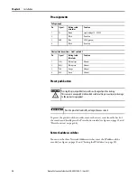
Electrical wiring instructions
Three electrical connections are located on the back of the housing.
A 4-pin M12 connector is used for the power supply connection.
Two 4-pin M12 connectors are used for the ethernet connection. The Link 1
connection is used for star networks. For ring networks, use both the Link 1 and
Link 2 connectors. In a linear network, use Link 1, Link 2, or both connectors.
Face mount flange
10 x 19 mm
Servo flange
6 x 10 mm
Blind hollow shaft
8, 19, 12, 15 mm and 1/4, 1/2, 3/8, 5/8 in.
ATTENTION
Switch off the power supply. The machine/system could unintentionally start while
you are connecting the devices.
Ensure that the entire machine/system is disconnected during the electrical
installation.
ATTENTION
Commissioning requires a thorough check by authorized personnel!
Before you operate a system equipped with the 842E EtherNet/IP absolute encoder,
make sure that the system is first checked and released by authorized personnel.
Please read more in Chapter 1, Safety.
Net
Mod
Link 1
Link 2
Encoder
Network
Address
Switches
x1
x10
x100
Reset
Button
Power connection
Link 1 connection
Network address
switches
Link 2 connection
Preset push button
Summary of Contents for Rockwell Automation 842E-MIP Series
Page 1: ...842E EtherNet IP Absolute Encoder 842E SIP xxx 842E MIP xxx User Manual ...
Page 6: ...iv Rockwell Automation Publication 842E UM001B EN P April 2015 About this document Notes ...
Page 34: ...28 Rockwell Automation Publication 842E UM001B EN P April 2015 Chapter 4 Installation Notes ...
Page 83: ......


