Installing the PLC2/DHII Interface
Chapter 4
48
The MAC board has two switches. Set Switch 1 to the UP position.
Switch 2 is not used and can be in either position. To set the switch,
follow these steps:
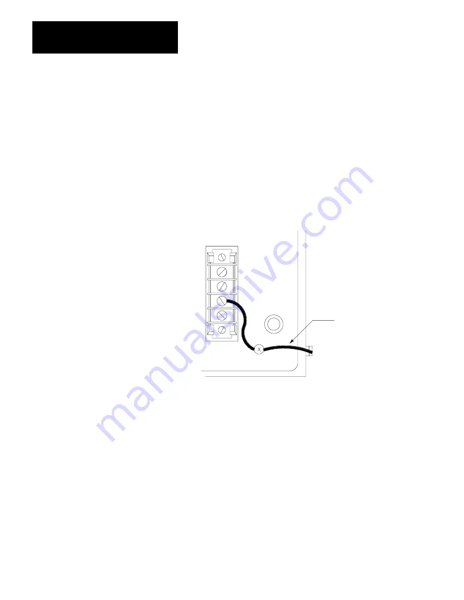
1. With the removable frame in the switch-setting position, disconnect
the green equipment-grounding conductor from between the
stationary frame and the ground post on the removable frame
(Figure 4.5).
Figure 4.5
Green Conductor Connecting the Stationary Frame to the Ground Post on the Removable
Frame
115V AC/230V AC
L1
L2/N
GND
INTERNALLY
SWITCH
SELECTABLE
Green Grounding
Conductor
2. While holding the removable frame at the top and bottom, lift in up
an inch and then out away from the stationary frame.
3. Locate the switches at the rear edge of the MAC board (middle
board) between the bottom two ribbon cables (Figure 4.6).
4. Set the switch with your finger.
5. Slide the removable frame back onto the stationary frame.
6. Push the removable frame back to the operating position.
7. Reconnect the green conductor for grounding the stationary frame to
the ground post on the removable frame (Figure 4.5).
Setting MACBoard Switches


