background image

Installation Instructions
Block I/O
Cat. No. 1791-0A32 Series B

7

1747-SN

Ra

1771-SN

Ra

PLC–2

Ra

PLC–5

Ra

PLC–5/250

Ra

PLC–3

Ra

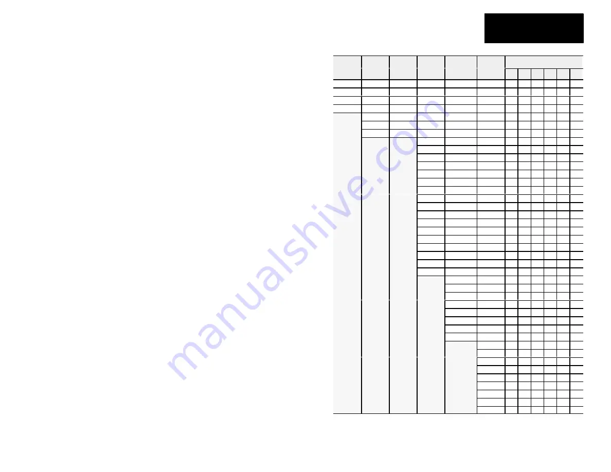
SW1 Switch Position

Rack

Number

Rack

Number

Rack

Number

Rack

Number

Rack

Number

Rack

Number

8

7

6

5

4

3

Rack 0

Rack 1

Rack 1

Not Valid

Rack 0

Rack 0

0

0

0

0

0

0

Rack 1

Rack 2

Rack 2

Rack 1

Rack 1

Rack 1

0

0

0

0

0

1

Rack 2

Rack 3

Rack 3

Rack 2

Rack 2

Rack 2

0

0

0

0

1

0

Rack 3

Rack 4

Rack 4

Rack 3

Rack 3

Rack 3

0

0

0

0

1

1

Rack 5

Rack 5

Rack 4

Rack 4

Rack 4

0

0

0

1

0

0

Rack 6

Rack 6

Rack 5

Rack 5

Rack 5

0

0

0

1

0

1

Rack 7

Rack 7

Rack 6

Rack 6

Rack 6

0

0

0

1

1

0

Rack 7

Rack 7

Rack 7

0

0

0

1

1

1

Rack 10

Rack 10

Rack 10

0

0

1

0

0

0

Rack 11

Rack 11

Rack 11

0

0

1

0

0

1

Rack 12

Rack 12

Rack 12

0

0

1

0

1

0

Rack 13

Rack 13

Rack 13

0

0

1

0

1

1

Rack 14

Rack 14

Rack 14

0

0

1

1

0

0

Rack 15

Rack 15

Rack 15

0

0

1

1

0

1

Rack 16

Rack 16

Rack 16

0

0

1

1

1

0

Rack 17

Rack 17

Rack 17

0

0

1

1

1

1

Rack 20

Rack 20

Rack 20

0

1

0

0

0

0

Rack 21

Rack 21

Rack 21

0

1

0

0

0

1

Rack 22

Rack 22

Rack 22

0

1

0

0

1

0

Rack 23

Rack 23

Rack 23

0

1

0

0

1

1

Rack 24

Rack 24

Rack 24

0

1

0

1

0

0

Rack 25

Rack 25

Rack 25

0

1

0

1

0

1

Rack 26

Rack 26

Rack 26

0

1

0

1

1

0

Rack 27

Rack 27

Rack 27

0

1

0

1

1

1

Rack 30

Rack 30

0

1

1

0

0

0

Rack 31

Rack 31

0

1

1

0

0

1

Rack 32

Rack 32

0

1

1

0

1

0

Rack 33

Rack 33

0

1

1

0

1

1

Rack 34

Rack 34

0

1

1

1

0

0

Rack 35

Rack 35

0

1

1

1

0

1

Rack 36

Rack 36

0

1

1

1

1

0

Rack 37

Rack 37

0

1

1

1

1

1

Rack 40

1

0

0

0

0

0

Rack 41

1

0

0

0

0

1

Rack 42

1

0

0

0

1

0

Rack 43

1

0

0

0

1

1

Rack 44

1

0

0

1

0

0

Rack 45

1

0

0

1

0

1

Rack 46

1

0

0

1

1

0

Rack 47

1

0

0

1

1

1

Rack 50

1

0

1

0

0

0

Summary of Contents for 1791-0A32 B Series

Page 1: ... 5 3 35 85 1 6 95 176 5 6 60 167 6 0 5 12 7 6 95H x 4 35W x 3 85D 176 5H x 110 5W x 98D Inches Millimeters Equipment Grounding Stud CAUTION When tightening grounding stud nut do not exceed 15 in lbs Block Operating temperature in air gap below module must not exceed 60oC 140oF 2 0 50 8 air gap on all 4 sides 30 1 1791 0A32 120V ac OUTPUT OUT OUT 00 01 02 03 04 05 06 07 10 11 12 13 14 15 16 17 00 0...

Page 2: ...ed with your module Select the proper module designation labels PLC or SLC for the front door and terminal strips 1 Remove labels from package Select correct labels for your application PLC label is numbered 00 07 and 10 17 SLC is numbered 00 07 and 08 15 3 Open clear front door Insert module designation label into slots in door 2 Remove plastic cover on terminal strip by flexing in middle Slip th...

Page 3: ... 14 out 15 out 16 out 11 out 17 L1 1 CLR L1 1 connections must be externally connected together to accommodate total amperage L1 2 connections must be externally connected together to accommodate total amperage L1 3 connections must be externally connected together to accommodate total amperage L1 4 connections must be externally connected together to accommodate total amperage Output fusing is re...

Page 4: ... amperage L1 2 connections must be externally connected together to accommodate total amperage L1 3 connections must be externally connected together to accommodate total amperage L1 4 connections must be externally connected together to accommodate total amperage Output fusing is recommended Refer to Table D NOTE 1 2 29 30 L1 1 L1 1 L1 2 L1 2 L1 2 L1 3 L1 3 L1 3 L1 4 L1 4 L1 4 The block I O modul...

Page 5: ...7 PLC Output 00 thru 07 SLC Output 00 thru 07 15 13 11 9 7 5 3 1 Output G 1 7 L1 3 L1 output supply 21 19 174 Output G 1 7 PLC out 10 thru 17 SLC out 08 thru 15 PLC Output 10 thru 17 SLC Output 08 thru 15 16 14 12 10 8 6 4 2 L1 4 L1 output supply 22 20 185 Not used For internal test only not for customer use 4 5 29 27 26 No Conn No internal connection customer can use 30 28 25 24 23 1 Connect chas...

Page 6: ...switches Only block I O modules with all inputs or all outputs can use complementary I O Installation Instructions Block I O Cat No 1791 0A32 Series B 6 Figure 6 Switch Settings SW2 8 Not used SW2 7 Not Used SW2 6 Last I O Group PLC 2 only 0 Not last rack 1 Last rack SW2 5 Processor Restart Lockout PRL 0 Processor Restart 1 Processor Lockout SW2 4 Hold Last State 0 Reset Outputs 1 Hold Last State ...

Page 7: ...12 Rack 12 Rack 12 0 0 1 0 1 0 Rack 13 Rack 13 Rack 13 0 0 1 0 1 1 Rack 14 Rack 14 Rack 14 0 0 1 1 0 0 Rack 15 Rack 15 Rack 15 0 0 1 1 0 1 Rack 16 Rack 16 Rack 16 0 0 1 1 1 0 Rack 17 Rack 17 Rack 17 0 0 1 1 1 1 Rack 20 Rack 20 Rack 20 0 1 0 0 0 0 Rack 21 Rack 21 Rack 21 0 1 0 0 0 1 Rack 22 Rack 22 Rack 22 0 1 0 0 1 0 Rack 23 Rack 23 Rack 23 0 1 0 0 1 1 Rack 24 Rack 24 Rack 24 0 1 0 1 0 0 Rack 25 R...

Page 8: ...1 Rack 62 1 1 0 0 1 0 Rack 63 1 1 0 0 1 1 Rack 64 1 1 0 1 0 0 Rack 65 1 1 0 1 0 1 Rack 66 1 1 0 1 1 0 Rack 67 1 1 0 1 1 1 Rack 70 1 1 1 0 0 0 Rack 71 1 1 1 0 0 1 Rack 72 1 1 1 0 1 0 Rack 73 1 1 1 0 1 1 Rack 74 1 1 1 1 0 0 Rack 75 1 1 1 1 0 1 Rack 76 1 1 1 1 1 0 Not Valid 1 1 1 1 1 1 Rack address 77 is an illegal configuration PLC 5 11 processors can scan rack 03 PLC 5 15 and PLC 5 20 processors ca...

Page 9: ...tible with the 1747 DSN Distributed I O Scanner module Termination Resistor A termination resistor must be installed on the last block in a series Connect the resistor as shown in Figure 7 Figure 7 Installing the Termination Resistor Termination Resistor Connect termination resistor across terminals 6 BLU and 8 CLR 10835 I BLU SHD CLR 150 ohm 57 6K and 115 2K baud 82 ohm 230 4K baud ATTENTION Devi...

Page 10: ... valid frames addressed to block 20ms idle time exceeded COMM and STATUS will alternately flash when processor restart lockout is selected a fault has occurred and the processor is communicating with the block Fusing The block I O module is internally fused to protect the module No external power fusing is required The outputs of the block I O modules are not fused Fusing of outputs is recommended...

Page 11: ...50mA 10A for 50ms 1 These surge ratings are for non fused outputs only 1791 0A32 Specifications Output Specifications Outputs per Block 32 4 groups of 8 Output Voltage Range 20 132V ac 47 63Hz Output Current Rating Vertical Mtg Horizontal Mtg 300mA 60oC 600mA 30oC 150mA 60oC 300mA 30oC Surge Current 10A for 50ms each repeatable every 2 sec Minimum On state Current 50mA per output Maximum On state ...

Page 12: ...mental Conditions Operational Temperature Storage Temperature Relative Humidity 0 to 60oC 32 to 140oF 40 to 85oC 40 to 185oF 5 to 95 noncondensing Conductors Wire Size Category 14 gauge stranded maximum 3 64 inch insulation maximum 11 1 You use this conductor category information for planning conductor routing as described in the system level installation manual With offices in major cities worldw...

Reviews: