Installation Instructions
Block I/O
Cat. No. 1791-0A32 Series B
4
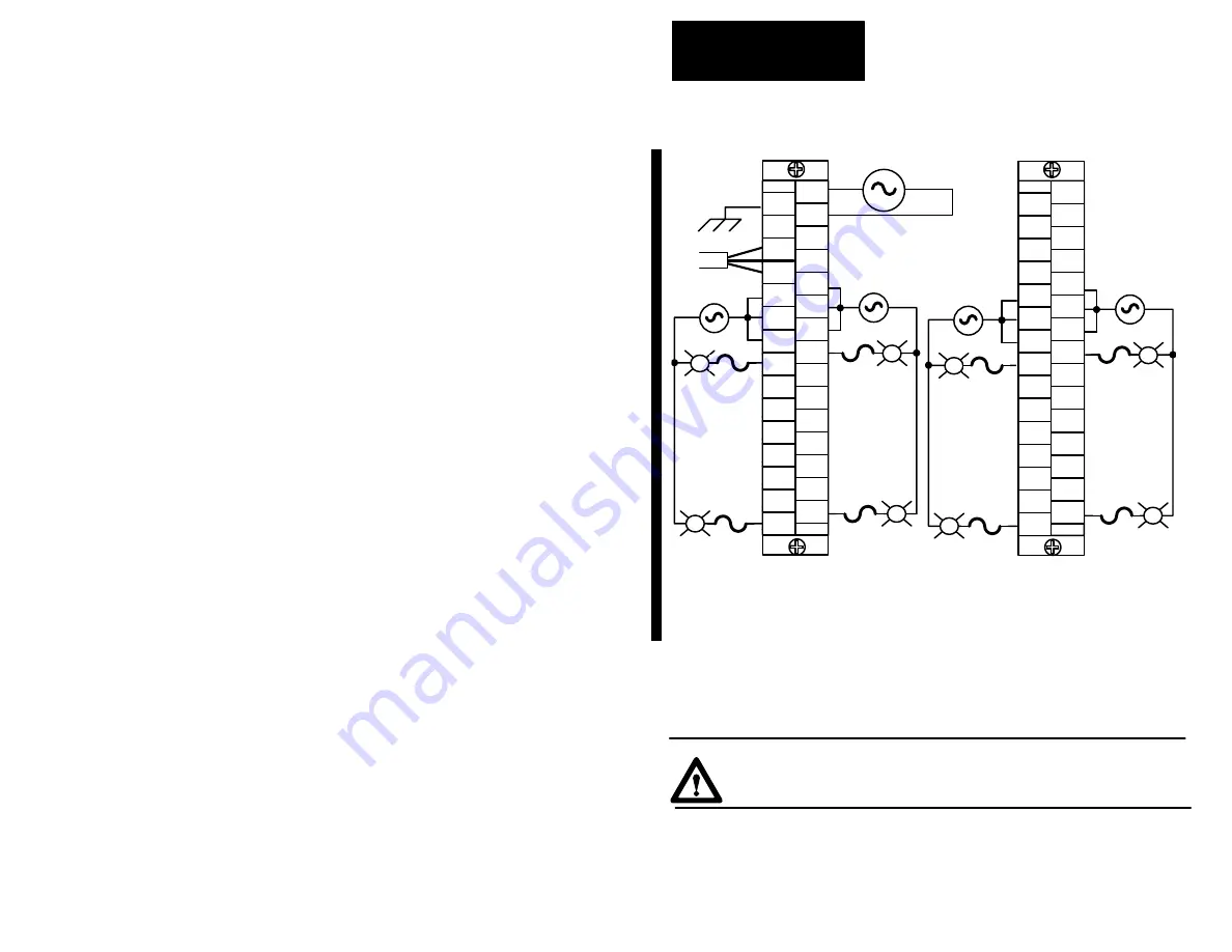
Figure 5
Wiring Connections with SLC Family Processors (refer to Table B)
L2/N
L1
RIO
L2/N
L1
1
30
SLC
L1
GND
N
NOT
USED
NOT
USED
BLU
SHD
out 00
out 01
out 02
out 03
out 04
out 05
out 06
out 07
out 08
out 10
out 11
out 12
out 13
out 14
out 09
out 15
L1–1
CLR
NOT
USED
L2/N
L1
NOT
USED
NOT
USED
NO
CONN
NO
CONN
NO
CONN
NO
CONN
NO
CONN
L2/N
L1
L2/N
L1
out 00
out 01
out 02
out 03
out 04
out 05
out 06
out 07
out 08
out 10
out 11
out 12
out 13
out 14
out 09
out 15
30
1
1
2
29
30
L1–1 connections must be externally connected together to accommodate total amperage.
L1–2 connections must be externally connected together to accommodate total amperage.
L1–3 connections must be externally connected together to accommodate total amperage.
L1–4 connections must be externally connected together to accommodate total amperage.
Output fusing is recommended. Refer to Table D.
NOTE:
1
2
29
30
L1–1
L1–1
L1–2
L1–2
L1–2
L1–3
L1–3
L1–3
L1–4
L1–4
L1–4
The block I/O module has an equipment grounding stud on the lower left side of
the module. Connect this grounding stud to your equipment ground. Torque the
nut to 15 in-lbs maximum when connecting to your equipment ground.
ATTENTION:
Do not overtighten the nut on the grounding stud
when connecting the wire. Damage to the module could result.
Refer to “Programmable Controller Wiring and Grounding Guidelines”
(1770-4.1) for further information.


