Inputs, Outputs and Adjustments
Chapter 5
5-28
Torque Command Input (TB2, Terminals 15, 16)
Terminals 15 and 16 provide a small amount of input filtering for operating
the controller in a torque block or velocity feedforward mode. A
±
3V DC
command equals 100% of the S1 current setting (i.e. motor rated current).
The buffered output of the command at terminal 4 of TB2 can be
connected to terminal 16 if more filtering is desired.
Spares (TB2, Terminals 18-20)
Reserved for future use and are not to be used.
Terminal Block - TB3 (A Quad B Board)
Figure 5.1 provides interconnect information between the position
controller and TB3 on the A Quad B Board.
ATTENTION: To guard against possible damage to the A
Quad B Board, assure that wiring between TB3 and the position
controller is correct. Refer to Figure 5.1.
!
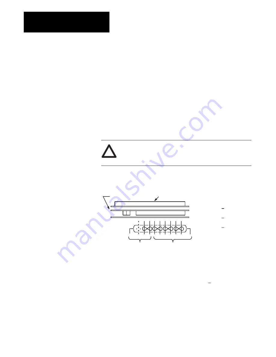
Figure 5.1
A Quad B Board Wiring
Important: Note terminal orientation prior to wiring.
1
TB2
20
10
TB3
1
1
Recommended Wire – Belden #9728 or equivalent. Maximum distance between the A Quad B
Board and the position controller is 40 feet (12.2 meters) using a 5 volt signal. For distances up
to 300 feet (91 meters), 18 AWG (0.8 mm
2
) wire and an 8 to 15V DC power supply must be used.
2
For proper operation when interconnecting to IMC products, the B and B (NOT) signals must be
reversed.
When interfacing to IMC 121 or 123 controllers, use the 1391-CAQB cable.
TB3
Num-
ber
1
2
3
4
5
6
7
8
9
10
Description
A
A (NOT)
B
2
B (NOT)
2
Z
Z (NOT)
+5V DC (
±
5%)
Signal Common
+8 to +15V DC
In
No Connection
A Quad B Board
To Position
Controller
1
Power
Supply
Input
1
9
8
7
6
5
4
3
2
1
2 1
S3
Top Logic Control Board
The A Quad B option operates in the same manner as the Allen-Bradley
845H Line Driver Encoder (26LS31 line driver output). The option
requires either a reg5V DC at terminal 7 or an unreg8 to
+15V DC input at terminal 9 (board draws 125mA maximum). The pulse
train output is selectable to 256, 512, 1024 or 2048 lines per revolution via
the Encoder Output switch, S3 (see page 5-36).
Summary of Contents for 1391B Series
Page 8: ...Introduction Chapter 1 1 6 End of Chapter...
Page 19: ...Receiving Unpacking and Inspection Chapter 3 3 17 End of Chapter...
Page 27: ...Description of Operation Chapter 4 4 25 End of Chapter...
Page 55: ...The 1326 AC Servomotor Chapter 8 8 57 End of Chapter...
Page 63: ...Transformers and Shunt Regulators Chapter 9 9 61 End of Chapter...
Page 71: ...Troubleshooting Chapter 10 10 69 End of Chapter...
Page 80: ...Cable Information Appendix C C 78 End of Appendix...
Page 82: ...Controller Options Appendix D D 80 End of Appendix...


