background image

iDR MixRack

  Getting Started Guide 

 AP7445 iss.3 


Switch power on 

Switch on the MixRack and Surface by pressing their rear panel power 
ON switches.  If you need to switch them on one at a time then switch 
on the MixRack first.  Also switch on any connected iPS10 backup 

supplies.  The system remembers the settings on power down.  These 
are restored when you switch the system on. 

Boot up time 

It takes around 15 seconds for the DSP to start passing audio with the 
same settings as at last power down.  You should hear the relays click 

as they connect the outputs once the MixRack has booted.  The Surface 
will light up and take control around 1 minute later, and the 
TouchScreen should be ready another minute after that.  Editor running 
on a laptop takes around 2 minutes to connect. 

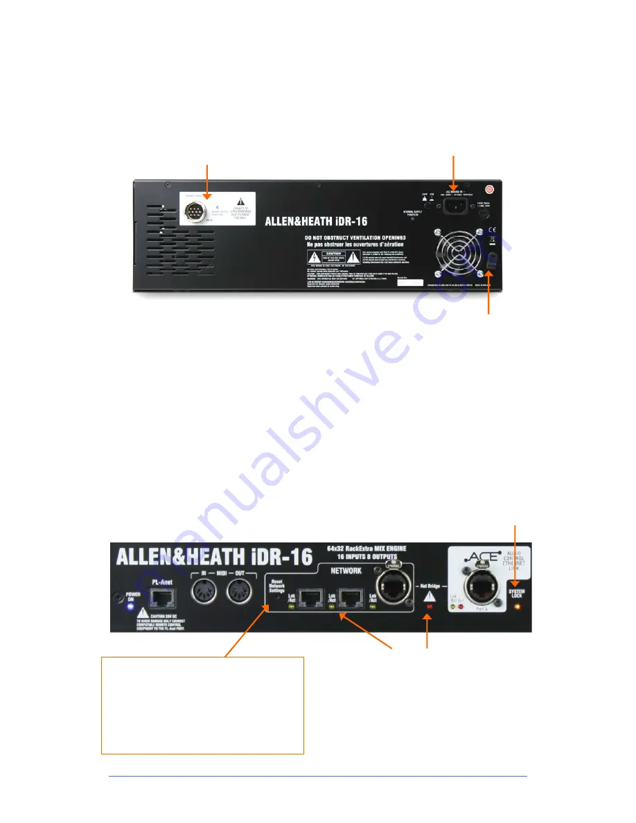
Status indicators 

Once booted, check that the blue POWER ON indicators are lit and that 

the various system status LEDs indicating correctly. 

SYSTEM LOCK

    Indicates 

that the audio is sync 
locked to the selected 
clock source.  If this does 

not light up then check that 
the correct Audio Clock 
Source has been selected 
using the Surface 

MIXRACK SETUP


screen 

or Editor.


The yellow 

Lnk/Act

 LEDs for connected sockets 

flash at a steady rate once the network link is 
established.  

If one or more pulse at a slow rate or the 

red error 

indicator

 remains lit then check that the cables are 

correctly plugged in and are not faulty. 

The red error LED will light to indicate network 
collision if you connect both ACE™ and NETWORK 
to the Surface using two cables. 


BACKUP SUPPLY

    DC  input  for  plugging  in  the 

iPS10

 redundant backup power supply unit.  

Rotate the plug until it locates in the socket, then 
tighten the locking ring.  There is no need to use 

the CAT5 cable provided with the iPS10 with 
these MixRacks.  

The MixRack will automatically switch between 
the supplies without interruption to the audio 

should one fail or lose power. 

MAINS INPUT

  Power ON/OFF press switch, 

protection fuse and power ON indicator. 

Note:

   Heed the safety warnings printed on the 

panel and Safety Sheet provided with the MixRack. 

Note:


Do not obstruct the fan or the ventilation 

slots on the rear and sides of the MixRack.

  The 

fan will increase in speed as the temperature rises. 

Mains cable securing clip


Loop the mains cable 
through the plastic clip 
provided.  For added 

security you can refit the 
clip using the screw to lock 
the cable in place. 

Reset Network Settings


To reset the MixRack TCP/IP address first turn 

the system off.  While using a thin, pointed 
object to press and hold in the recessed 
switch, turn the MixRack back on.  Hold the 
switch in for at least 15 seconds while it 

reboots. 

Summary of Contents for iDR-16

Page 1: ...Fixed Format MixRacks iDR 16 iDR 32 iDR 48 iDR 64 Getting Started Guide Publication AP7445...

Page 2: ...quick start information for the fixed format iLive Series iDR 16 iDR 32 iDR 48 and iDR 64 MixRacks The modular iDR10 and iDR0 MixRacks are referred to here but please see their user guides for furthe...

Page 3: ...option for digital mic splitting and system linking Choose from ACE ES MADI ADAT Aviom and more 64x32 RackExtra DSP engine with 8 stereo FX processors 32 buses can be configured as mono stereo groups...

Page 4: ...onitor systems with digital mic split 3U fixed format MixRack 16 mic line in 8 XLR out ACE single CAT5 Surface link Port B network option slot External redundant supply option iDR 32 Equivalent to a 3...

Page 5: ...port at the Surface For more information about MIDI refer to the iLive MIDI Specification Network Built in 3 port switch Connect one or more laptops running iLive Editor a wireless router other iLive...

Page 6: ...d any other network devices such as a wireless router and laptop need compatible network addresses Factory defaults are MixRack 192 168 1 1 Sub mask 255 255 255 0 Surface 192 168 1 2 TouchScreen 19216...

Page 7: ...the network link is established If one or more pulse at a slow rate or the red error indicator remains lit then check that the cables are correctly plugged in and are not faulty The red error LED wil...

Page 8: ...Capable of 64 channel bi directional digital audio transmission at the iLive sampling rate of 48kHz Fit none or one of the option cards available from Allen Heath Use for Digital mic splitter to link...

Page 9: ...ternal using the MIXRACK SETUP Mix Pref screen This example shows a compact two engineer system with wireless laptop controlling monitor mixes Alternatively you could connect another Surface to the iD...

Page 10: ...ACE 1 to Slave port A ACE Refer to Allen Heath web site for recommended cable type and maximum length Step 3 Set up Dual Rack system Using the Surface TouchScreen go to Utility Network Dual MixRack S...

Page 11: ...M iDR 16 32 48 64 USER EXT IN SOURCE RACKEXTRA x8 FX RACK max TALKBACK SIG GEN SINE PINK WHITE BP NOISE TALKBACK EXT INPUT DIGITAL TRIM MAIN MIX CONFIG iDR 32 32 MIC LINE INPUTS iDR 48 48 MIC LINE INP...

Page 12: ...he equipment has not been subject to misuse either intended or accidental neglect or alteration other than as described in the User Guide or Service Manual or approved by ALLEN HEATH Any necessary adj...

Reviews: