2
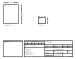
TEMPLATE
FALCON F-SERIES LOCKS
IMPORTANT:
NOTCHES REQUIRED
IN EXTERIOR SIDE OF
DOOR FOR LOCK TO
MOUNT & FUNCTION
PROPERLY.
FIRST:
BORE 2
¹⁄₈
” (54mm) HOLE AT CORRECT BACKSET
SECOND:
BORE LATCH HOLE
PARALLEL TO
SIDES 1” (25mm)
DISTANCE
FROM EDGE
OF DOOR
(BACKSET)
FOLD ALONG EDGE OF DOOR
HEIGHT
LINE
⁵⁄₃₂
” (4mm)
x
³⁄₃₂
” (2mm)
DEEP
2
³⁄₄
”
(70mm)
2
³⁄₄
”
(
60mm
)
Center
for 1
³⁄₈
”
(35mm)
DOORS
Center
for 1
³⁄₄
”
(44mm)
DOORS
RECOMMENDED TEMPLATE INSTRUCTIONS MUST
BE FOLLOWED TO ASSURE PROPER FUNCTION
8.
INSTALL INSIDE TRIM
A.
Snap rose over mounting plate.
B.
Place lever on spindle and slide to
locking button.
C.
Push lever in until button engages
hole in lever.
D.
Check function before closing door.
9.
REMOVING STANDARD
CYLINDERS & LEVERS
A.
Insert key and turn 90°
counter-clockwise to unlock lockset.
B.
Depress locking button and pull off lever
and cylinder.
MOUNTING
PLATE
ROSE
LEVER
LOCKING
BUTTON
LOCKING
BUTTON
10.
INSTALLING STANDARD
CYLINDERS & LEVERS
A.
Insert cylinder into lever.
B.
Insert key into cylinder.
C.
With notches of key facing up, align hole in
lever with locking button on spindle assy and
slide lever to locking button.
D.
Push lever until lever engages button.
E.
Check function before closing door.
LOCKING
BUTTON
HOLE
11.
REMOVING IC CORE
A.
Unlock lockset.
B.
Turn control key 15 degrees
clockwise until key stops.
C.
Pull key to remove IC core.
LOCKING
BUTTON
12.
REMOVING IC LEVERS
A.
With IC core removed, depress locking button
and pull lever to remove.
13.
INSTALL IC LEVERS
A.
Slide tailpiece assembly into spindle,
engaging the single leg with the drive cam
in the spindle.
B.
Insert spindle cap into the lever, notched
end first.
C.
Push lever in until locking button
engages hole in lever.
D.
With control key in core rotate key 15°
clockwise and insert fully into lever. Turn the
key counter-clockwise and remove key.
E.
Check function before
closing door.
TAILPIECE
ASSEMBLY
SPINDLE
CAP
14.
TAILPIECE INSTALLATION
A.
Insert spring and pin into cylinder.
B.
Place tailpiece into cap.
C.
Thread cap onto the cylinder.
NOTE:
The cap must be properly adjusted. If
too loose, excessive plug end play will prevent
the key from being withdrawn. If too tight, the
plug will drag and be difficult to rotate with the
key.
CYLINDER
SPRING
PIN
TAILPIECE
CAP
2
¹⁵⁄₃₂
”
(63mm)
MAX
REMOVE TEMPLATE FROM INSTRUCTIONS


