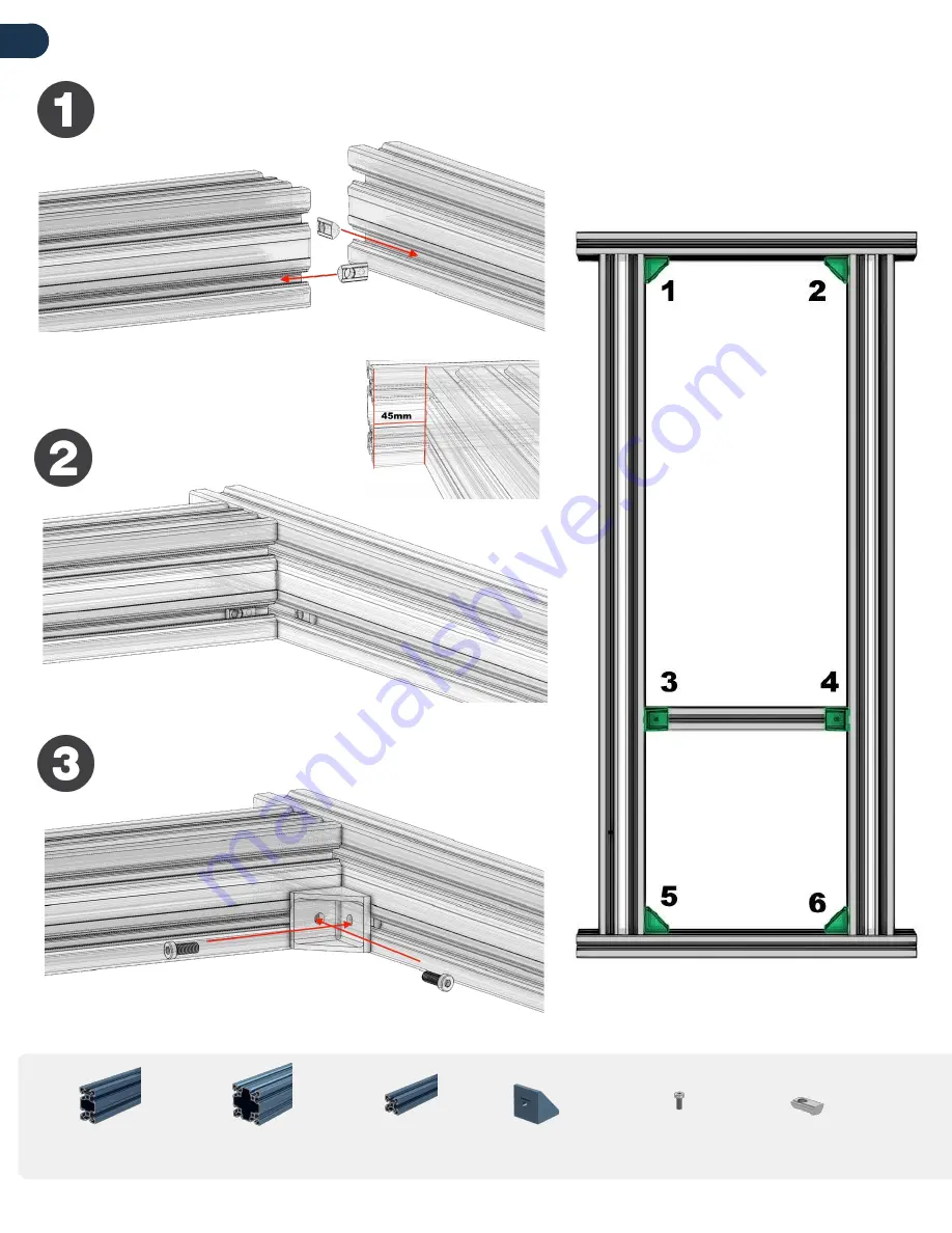
01
BASE ASSEMBLY
Page
2
ST-EXT-001-0405
ST-HP-003-0001
ST-EXT-005-13
05
ST-EXT-002-0675
HW-FN-003-0018
HW-FN-002-0001
2 x
1 x
6 x
12 x
Repeat the process for the positions below
Page 1: ...pit crew is here to support you allin1gaming com support allin1gaming com Skype Us info allin1gaming com Assembly Instructions Pro Sim Frame chat with a live agent allin1gaming email our team support...
Page 2: ...01 BASE ASSEMBLY Page 2 ST EXT 001 0405 ST HP 003 0001 ST EXT 005 1305 ST EXT 002 0675 HW FN 003 0018 HW FN 002 0001 2 x 2 x 1 x 6 x 12 x 12 x Repeat the process for the positions below...
Page 3: ...02 SIM FEET ASSEMBLY Page 3 HW FN 003 0020 HW FN 002 0001 4 x 4 x 28 x 28 x HW LF 008 0001 MT BP 001 Repeat the process for the positions below 4 x HW FN 008 0002...
Page 4: ...03 UPRIGHT ASSEMBLY ST HP 003 0001 ST HP 003 0004 HW FN 003 0018 Page 4 ST EXT 002 0720 HW FN 002 0001 24 x 2x 24x 2x 4x...
Page 5: ...Page 5 ST HP 003 0001 ST EXT 002 0585 ST EXT 001 0360 HW FN 002 0001 8 x 1 x 1 x 8 x 4 x 04 SIDE MOUNT ASSEMBLY HW FN 003 0018...
Page 6: ...W FN 002 0001 4 x FANATEC SIDE MOUNT DELUXE SIDE MOUNT ST HP 003 0001 HW FN 003 0018 8 x 4 x HW FN 002 0001 8 x Repeat step 1 for the remaining 4 brackets Add 4 t nuts into the slots of the 180mm prof...
Page 7: ...05 FRONT WHEEL MOUNT ASSEMBLY Page 7 front 1 x 1 x 8 x MT WH 001 MT FW 001 HW FN 008 0003 HW FN 015 0025 HW FN 015 0030 4 x 4 x 25mm 30mm 30mm 25mm MT WH 002 1 x ST GP 003 0001 4 x...
Page 8: ...Page 7 deck HW FN 015 0025 8 x HW FN 008 0003 8 x HW FN 001 HW FN 002 HW WD 001 1 x 1 x 1 x 05 WHEEL DECK MOUNT ASSEMBLY ST GP 003 0001 4 x...
Page 9: ...FANATEC PODIUM MOUNT ASSEMBLY 1 x MT WH 001 HW FN 015 0025 8 x MT WH 002 1 x Page 7 Fanatec 1 x 1 x MT PD 001 MT PD 002 ST EXT 002 0187 2 x 4 x HW FN 003 0020 do step 3 after 1 2 om the following pag...
Page 10: ...05a ATTACH WHEEL MOUNT TO UPRIGHTS Page 8 HW FN 003 0020 8 x HW FN 002 0001 8 x...
Page 11: ...06 SEAT MOUNT ASSEMBLY ST EXT 001 0495 Page 9 HW FN 003 0018 12 x HW FN 002 0001 12 x ST GP 003 0001 4 x 2 x ST HP 003 0001 4 x ST GP 003 0001 ST HP 003 0001 Optional With Undermount Seating Kit...
Page 12: ...Align the center T nut with the center hole of the the pedal mount and tighten with a screw Slide in the remaining T nuts so that they align with the red circles as indicated in the photo Repeat the...
Page 13: ...slots as in the photo Secure a flathead screw into center hole of each profile Leave the 45x45 profile slightly loose as it might need to be adjusted to fit your pedal set 07b ADD PEDAL MOUNT HARDWARE...
Page 14: ...s are aligned Once aligned remove pedal set and tighten 45x45 profile Center screw acts as a pivot Keep in place when rotating and adjust positions of the other screws 1 outside hole rotation results...
Page 15: ...gle and height that you choose follow the same steps above changing only the t nut layout from step 4 from page 12 and screw positions from steps 2 3 from page 14 07c PEDAL MOUNT FREESTYLE METHOD Exam...