Summary of Contents for Ruptair F Series

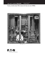
Page 1: ... i h r i i INSTRUCTION BOOK i 4 v tv 1 TYPE F MOVABLE PORTION FC 150 250 500 RUPTAIR MAGNETIC POWER CIRCUIT BREAKER AND AUXILIARY EQUIPMENT STORED ENERGY OPERATOR t September 1 1966 Book No 6630 2 5 o 1 tt t a Courtesy of NationalSwitchgear com ...

Page 2: ...ATCH CLOSING LATCH TRIPPING AND CLOSING SOLENOID AUXILIARY EQUIPMENT AUXILIARY SWITCH INTERLOCK PLUNGER OPERATOR CONTROL RESET RELAY 3 9 3 1 0 7 3 1 1 i 3 12 3 1 3 3 1 4 vs 3 15 NS 3 16 3 1 7 v PART 4 DISCONNECT SECTION vs 4 1 BREAKER MECHANISM CONTACTS SERVICING CONTACTS BREAKER T I M I N G ARCING CONTACT HINGE JOINT CONTACT PRESSURE ON HINGE JOINT CONTACT ALIGNMENT CONTACT LEAD CONTACT STROKE Vi...

Page 3: ... OPERATOR ADJUSTMENTS FIGURE 8 72 320 033 4 01 TYPICAL CONTROL SWITCH 71 301 758 FIGURE 11 TYPICAL AUXILIARY SWITCH 71 116 481 FIGURE 13 TYPICAL OPERATOR LINKAGE DIAGRAM 14 15 205399 LEFT FRONT VIEW OF TYPE F AIR MAGNETIC CIRCUIT BREAKER WITH TYPE SE 3 STORED ENERGY OPERATOR 205397 MANUAL CLOSING DEVICE 205391 VIEW SHOWS APPLICATION OF FIFTH WHEEL ON TYPE F AIR MAGNETIC CIRCUIT BREAKER 205396 VIEW...

Page 4: ...177 196 003 2 3 25 6 Hinge Contact Washer Arcing 1 05 71 177 196 005 3 12 3 17 Primary Contact Assembly 12 15 71 201 738 502 1 6 1 3 Y Relay Give Voltage 35 10 1 2 1 21 19 20 Closing Solenoid Coil Give Voltage 71 200 745 1 2 4 8 A t 23 00 Trip Solenoid Coil Give Voltage 71 209 234 1 2 4 49 3 20 Latch Check Switch W 666 303 1 2 5 47 16 60 Motor Cutoff Switch 71 210 390 801 1 2 5 60 138 15 Motor Giv...

Page 5: ...rent is being carried through the main contacts As the movable contact assembly separates from the stationary contact assembly the current transfers very quickly from the main contacts t o the arcing contacts thus keeping the main contact erosion to a minimum For breakers equipped with tertiary contacts the current transfers from the mains to the tertiary and then to the arcing contacts As the mov...

Page 6: ...evice of breaker should be used for preliminary operation to see that all parts are free and work smoothly The bushings and other insulating parts should be clean and dry All contact surfaces should be inspected to see that they are clean and smooth Do not dress silver surfaces Removal of all phase barriers and removal or raising of arc chute assemblies gives access to breaker for checking adjustm...

Page 7: ...mpression will be realized by an audible snap as roll 4 54 13 H drops back on latch 4 18 13 11 when cam 4 34 13 10 clears follower roll 4 35 13 J Continue to rotate handle until motor coupling rotates freely without load M VS v3 3o 3 CLOSING THE BREAKER Energizing the spring release coil 5 50 rotates arm 4 20 and latch 4 18 13 11 clockwise thereby releasing the closing springs The closing springs ...

Page 8: ...er 14 E is thereby released enabling link 14 6 to rotate clockwise about fixed center 14 F Since the restraining force on the breaker opening springs is now released they act to rotate crank arms 14 2 and 14 3 clockwise about fixed center 14 B and open the breaker Toggle linkages 14 4 and 14 5 collapse to their posi tion shown in Figure 15 if the closing springs are not charged If springs are char...

Page 9: ...e by screw 4 7 W Note that this adjustment affects the clearance between the i 3J 1 CLOSING LATCH Fig 4 Sr 5 sS The closing latch 5 18 should engage its roll 5 54 1 8 to 3 16 above the lower edge of the latch face Adjustment is made by screw 4 42 trip pin 5 50A and the arm 5 20 See Section 3 12 Note that this adjustment affects the clearance between the 10 TRIPPING AND CLOSING SOLENOID Fig 5 3 12 ...

Page 10: ...rely by pressing the contact to one side against the spring and rotating it within its insulated rotor housing until it snaps into the desired position v J 3 3 15 INTERLOCK PLUNGER Fig 1 The foot lever 1 20 operates the interlock plunger 1 18 as well as the trip latch and the closing latch Depressing the lever trips the breaker releases the closing spring and raises plunger 1 18 sufficiently to re...

Page 11: ...8 1 and 88 2 switch shutting off the motor When the closing springs are discharged the cam is freed and the reset spring 5 32 rotates the cam shaft releasing the switch which closes the motor circuit and starts the spring charge The 88 switch assembly is factory adjusted and pinned in position readjustment is required remove roll pin 2 loosen nut 3 and rotate the switch assembly clockwise as far a...

Page 12: ...ard circuit breaker control limits The time delay error caused by temperature is minor being less than 3 from 20 C to 80 C and not over 5 to 40 C The voltage regulator and timing circuits are mounted on a printed circuit board and incapsulated in a resilient material for shock resistance The controlled supply voltage charges the capacitor Cj through the time rate determining resistor R to the trig...

Page 13: ...age a t E exceeds a p r e c i s e level Vp I n other words the UJT does n o t a l l o w c u r r e n t t o f l o w from p o i n t E t o p o i n t B u n t i l the UJT i s turned on by t h e f i r i n g voltage Vp The v o l t a g e drop Vc across t h e terminals AB charges the capacitor C through the v a r i a b l e r e s i s t o r Rj The time t h a t i t takes the capacitor C t o charge t o the f i ...

Page 14: ...ducts even after the pulse is removed The relay contacts R close allow ng current to flow through the spring release coil circuit The gate terminal of the SCR is protected from random high frequency pulse by capacitor C2 which provides a short circuit to ground for these pulses capacitor C2 is negligible at high frequencies and the capacitor allows current to flow through it In other words the rea...

Page 15: ... g c o n t a c t s c o n t a c t s should be r e p l a c e d A V Hinge j o i n t s Remove t h e disconnect arms as a u n i t by removing screw 3 24 n u t 3 14 and s p r i n g washers 3 23 C a r e f u l l y i n s p e c t a l l c o n t a c t surfaces S i l v e r washers 3 25 and adjacent surfaces should be clean and f r e e o f roughness o r g a l l i n g Lubricate washers 3 25 and mating surfaces b...

Page 16: ... should normally be necessary i w The horizontal pairs of main contact fingers in each phase should make with the moving contact simultaneously Note Contacts on different phases should not necessarily make simultaneously they can vary as much as 1 32 inches ft o X If not already detached remove pin 1 46 and detach link 1 47 from disconnect arms 3 18 and 3 19 N i Sx c On MA 75 150B and FC 150 250 5...

Page 17: ...n the bottom contact fingers 3 11 and the contact on the disconnect arms 3 18 and 3 19 should be 7 32 to 1 4 inches Dimension b in View A A of Fig 3 Adjustment is made by opening or closing the gap with nut 3 1 Reconnect link 1 47 to disconnect arms 3 18 and 3 19 using pin 1 46 O r v X t 4 8 CONTACT STROKE Fig 3 X Contact stroke should be checked and adjusted only when the contacts are in proper a...

Page 18: ...ck w d The barrier stack 2 23 consisting of a number of refractory plates with Vee Shaped slots cemented together The barrier stack cools squeezes and stretches the arc to force a quick interruption X e The barrier 2 1 containing coolers 2 28 through which the by product gases of interruption pass The barrier completes the cooling and deionizing of the arc products NK X XN X Arc chutes are normall...

Page 19: ...ws are tightened securely on all three phases ft 5 4 BARRIER STACKS Fig 2 X The barrier stacks are fragile and should be handled carefully The barrier stacks should be inspected for erosion of the plates in the areas of the slots The stacks should be replaced when a milky glaze is observed on the full length of the edges of most of the slots They should be likewise replaced i f plates are broken o...

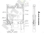
Page 20: ...POLE PIECE ARC RUNNER I ir ATt iny i I J P J j r i i 1 i in ARC RUNNER VC n x r RvC0IL Li FRONT fsVCORE COIL A REART M r i i 2 i i i A c 3 I C0RE I8 v m ft 21 WASHER I 1 73 o r in a 1 l 7 SUPPORT I i i 4 i P FIG 2 TYPICAL ARC CHUTE JANUARY 18 1962 71 401 442 401 ...

Page 21: ...UT SCREW 0 PLATE TUBE 2l VIEW A A ARCING CONTACTS ENGAGING R CV0NUT WASHER DISCONNECT ARM P H V2 WASHER o DISCON i 8 NECT ARM LH V 24VSCREW NUT 04 0 i SPRING VWASHER I n NOZZLE X SILVER 5 WASHER VIEW A A BREAKER LATCHED VIEW B B 2 m 73 A FIG 3 BREAKER OPEN VIEW A A MAIN CONTACTS ENGAGING TYPICAL STUD a SUPPORT JANUARY 22 1962 71 401 444 401 u ...

Page 22: ...LOCK ROD KEY 53 4 ARM CAM 34 SHIMS ROLL 54 SCREW a LOCKWASHER 38 A 6 VHEX NUT I MOTOR 48 n 49 SOLENOID TRIP X BOLT 24 36VSCREW SHIMS 25 LATCH 2 ARM m I JO 71 SCREW a NUT A i v no PIN SHIMS STOP SCREW CLDSING SPRINGS TUBE PLATE NUTS TUBE WASHER FIG 4 r TYPICAL STORED ENERGY OPERATOR 71 303 129 401 JUNE 20 1962 ...

Page 23: ...HIMS SPRING 32 55 R0LL TRIP in PIN 6 HEX NUT I SCREW 42 o 49 SOLENOID x STOP 30 ROLL SPRING RELEASE 50 SOLENOID TRIP 3 PIN m 9 LATCH 3 HEX NUT 60 I5 BLOCK in FIG 5 OPERATOR ADJUSTMENTS JUNE 27 1962 71 209 564 401 56 ROLL ARM 2 U ...

Page 24: ...ARGED INDICATING LIGHT CIRCUIT p t I 2 34 EEH 5 p fa s a F S oo B r A ML K EJ SWITCHES SHOWN IN THROWN POSITION 3 0 Q o in 2 I 3 4 0 0 Q a 0 o I n ARM 4 x OVERTRAVEL CAM 2 88 1 S WITCH 6 5 m 73 ROLL n r i U PIN y SWITCH R O L L 3 N U T F I G 8 TYPICAL CONTROL SWITCH 72 320 033 401 JULY 27 1966 ...

Page 25: ...NG STUD 4 M ROTOR ASSEMBLY in 7 BEARING I NUT n 3 ROTOR ASSEMBLY 8 J BUSHING z BARRIER M M m H m M M 9 l SHAFT BEARING 2 m 73 STATIONARY CONTACT 10 J CRANK m S m ARM in C TlU MOUNTING BRACKET MOUNTING BRACKET FIG 11 TYPICAL AUXILIARY SWITCH JULY 16 1958 71 301 758 ...

Page 26: ...H 6 5 G 7 LATCH 12 E 9 6 V F BREAKER CLOSING SPRINGS I n BREAKER OPEN SPRINGS CHARGEO fl WSAAfr X BREAKER CLOSEO SPRINGS DISCHARGED FIG 13 FIG 14 B I 2 A 2 m 3 II 73 LATCH C VI H 4 12 K LATCH I TYPICAL OPERATOR LINKAGE DIAGRAM E 6 F JUNE 1962 71 116 401 i J FIG 15 i ...

Page 27: ...i X S rr v V M Rr TWte Air Magnetic Circuit Breaker Left f r o n t view o f Type MFn w i t h Type SE 3 stored energy o p e r a t o r 205399 v i Courtesy of NationalSwitchgear com ...

Page 28: ...3SB51 r ALLIS CHALMERS o 205397 Manual Closing Device Courtesy of NationalSwitchgear com ...

Page 29: ...J ALUS CHALMERS A T v V IHaH i 3 v 5S 205391 View shows application of f i f t h wheel on Type F Air Magnetic C i r c u i t Breaker Courtesy of NationalSwitchgear com ...

Page 30: ... ALLIS CHALMERS t o s w r 205396 View shows application o f manual spring charging handle on Type F A i r Magnetic Circuit Breaker Courtesy of NationalSwitchgear com ...

Page 31: ...ving Phase Barriers Remove Channels l panel 2 and slide phase barrier assemblies 3 off front of breaker Tilting arc chutes Position arc chute support unfasten blowout coil connections and lowef end of arc chute tilt arc chutes back on supports is ...

Reviews: