background image

Setting up the monitor | 29

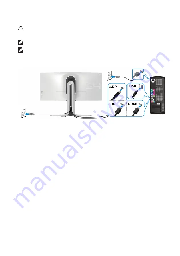
Connecting the computer

WARNING: Before you begin any of the procedures in this section, 

follow the 

Safety instructions

.

NOTE: Do not connect all cables to the computer at the same time.
NOTE: The images are for the purpose of illustration only. Appearance of 

the computer may vary.

To connect your monitor to the computer:

1.

Connect the other end of the DisplayPort cable (or Mini-DisplayPort to 

DisplayPort) or HDMI cable to your computer.

2.

Connect the other end of the USB 3.0 upstream cable to an appropriate 

USB 3.0 port on your computer.

3.

Connect the USB 3.0 peripherals to the USB 3.0 downstream ports on the 

monitor.

4.

Plug the power cables for your computer and monitor into a wall outlet.

5.

Turn on the monitor and the computer. 
If your monitor displays an image, installation is complete. If it does not 

display an image, see 

Universal Serial Bus (USB) specific problems

.

Summary of Contents for AW3420DW

Page 1: ...Alienware AW3420DW Monitor User s Guide Model AW3420DW Regulatory model AW3420DWb...

Page 2: ...mage to hardware or loss of data if instructions are not followed WARNING A WARNING indicates a potential for property damage personal injury or death 2019 Dell Inc or its subsidiaries All rights rese...

Page 3: ...y modes 15 Electrical specifications 16 Physical characteristics 16 Environmental characteristics 17 Power management modes 18 Pin assignments 19 Plug and Play capability 20 Universal Serial Bus USB i...

Page 4: ...vertical extension 47 Tilt and swivel extensions 47 Vertical extension 47 Using AlienFX application 48 Prerequisites 48 Installing AWCC through Windows update 48 Installing AWCC from the Dell Support...

Page 5: ...ow If any component is missing contact Dell technical support For more information see Contact Dell NOTE Some components may be optional and may not ship with your monitor Some features or media may n...

Page 6: ...es by country DisplayPort cable DisplayPort to DisplayPort Mini DisplayPort to DisplayPort cable USB 3 0 upstream cable enables the USB ports on the monitor Quick Setup Guide Safety Environmental and...

Page 7: ...ped with 1 USB upstream port and 4 USB downstream ports Plug and play capability if supported by your system On Screen Display OSD adjustments for ease of setup and screen optimization AW3420DW offers...

Page 8: ...Identifying parts and controls Front view Label Description Use 1 Cable management slot on the front side of the stand To organize the cables neatly 2 Power On Off button with LED indicator To turn t...

Page 9: ...e monitor 3 Barcode serial number and Service Tag label Refer to this label if you need to contact Dell for technical support 4 Cable management clip To organize the cables neatly 5 Stand release butt...

Page 10: ...To organize cables by routing them through this slot 10 I O cover Protects the I O ports Label Description Use 1 Power connector Connect the power cable shipped with your monitor 2 Line out port Conn...

Page 11: ...y setting is on so the downlights are active if the power cable is connected To change the default settings see AlienFX Lighting NOTE When the Spectrum function is On the downlights are turned off Mon...

Page 12: ...wer Charging Connect to charge your USB device 7 Headphone port Connect headphone or speakers 8 10 USB downstream ports 3 Connect your USB device NOTE To use these ports you must connect the USB cable...

Page 13: ...325 mm x 0 2325 mm Pixel per inch PPI 110 Viewing angle Vertical Horizontal 178 typical 178 typical Luminance output 350 cd m typical Contrast ratio 1000 to 1 typical Faceplate coating Anti glare with...

Page 14: ...rt playback 480p 576p 720p 1080p Connectivity 1 x DisplayPort version 1 2 rear 1 x HDMI port version 1 4 rear 1 x USB 3 0 upstream port rear 4 x USB 3 0 downstream ports bottom 2 rear 2 1 x headphone...

Page 15: ...50 Hz 56 25 50 148 5 1920 x 1080p 60 Hz 67 5 60 148 5 3440 x 1440 50 Hz 73 7 50 265 25 DP display modes Display mode Horizontal frequency kHz Vertical frequency Hz Pixel clock MHz Sync polarity Horiz...

Page 16: ...DMI 19 pins cable is not included Digital DisplayPort 20 pins Universal Serial Bus USB 9 pins NOTE Dell monitors are designed to work optimally with the video cables that are shipped with your monitor...

Page 17: ...m Non operating 12 192 m 40 000 ft maximum 375 3 BTU hour maximum 197 9 BTU hour typical Height extended 450 8 mm 17 75 in Height compressed 443 0 mm 17 44 in Width 561 5 mm 22 11 in Depth 273 8 mm 10...

Page 18: ...ess than 0 5 W Switch off Off Less than 0 3 W Power Consumption Pon 39 13 W Total Energy Consumption TEC 122 82 kWh Zero power consumption in OFF mode can only be achieved by disconnecting the main ca...

Page 19: ...yPort connector Pin number 20 pin side of the connected signal cable 1 ML3 n 2 GND 3 ML3 p 4 ML2 n 5 GND 6 ML2 p 7 ML1 n 8 GND 9 ML1 p 10 ML0 n 11 GND 12 ML0 p 13 GND 14 GND 15 AUX p 16 GND 17 AUX n 1...

Page 20: ...C DATA SDA 17 DDC CEC Ground 18 5V POWER 19 HOT PLUG DETECT Plug and Play capability You can connect the monitor to any Plug and Play compatible system The monitor automatically provides the computer...

Page 21: ...ed 5 Gbps 4 5 W Max each port High speed 480 Mbps 4 5 W Max each port Full speed 12 Mbps 4 5 W Max each port NOTE This monitor is Super Speed USB 3 0 compatible Up to 2 A on USB downstream port with b...

Page 22: ...tom Power charging port the port with icon supports up to 2 A fast charging capability if the device is BC1 2 compatible NOTE USB 3 0 functionality requires a USB 3 0 capable computer NOTE The USB por...

Page 23: ...n the list below when unpacking cleaning or handling your monitor To clean your anti static screen lightly dampen a soft clean cloth with water If possible use a special screen cleaning tissue or solu...

Page 24: ...y other source follow the set up instructions that were included with the stand CAUTION The following steps are important to protect your curved screen Do follow the instructions below to finish up th...

Page 25: ...itor 25 5 Open the protective cover on the monitor to access the VESA slot on the monitor 6 Slide the tabs on the stand riser into the slots on the display back cover and lower the stand assembly to s...

Page 26: ...r 7 Hold the stand riser and lift the monitor carefully then place it on a flat surface CAUTION Hold the stand riser firmly when lifting the monitor to avoid any accidental damage 8 Lift the protectiv...

Page 27: ...cable management clip on the back of the display 10 Connect the power cable to the monitor 11 Connect the necessary cables to the monitor HDMI cable optional cable is not included DisplayPort cable or...

Page 28: ...nized before the I O cover is attached CAUTION Do not plug the power cable into the wall outlet or turn on the monitor until you are instructed to do so 13 Slide the slots on the I O cover into the sl...

Page 29: ...onnect the other end of the DisplayPort cable or Mini DisplayPort to DisplayPort or HDMI cable to your computer 2 Connect the other end of the USB 3 0 upstream cable to an appropriate USB 3 0 port on...

Page 30: ...ipped with your monitor If you are attaching a stand that you purchased from any other source follow the set up instructions that were included with the stand To remove the stand 1 Turn off the monito...

Page 31: ...Setting up the monitor 31 6 Press and hold the stand release button 7 Lift the stand up and away from the monitor...

Page 32: ...emove the monitor stand See Removing the monitor stand 3 Use a Phillips crosshead screwdriver to remove the four screws securing the plastic cover 4 Attach the mounting bracket from the wall mounting...

Page 33: ...n left right to toggle between options 3 Press the joystick button again to confirm the settings and exit Joystick Description When the OSD menu is on press the button to confirm the selection or save...

Page 34: ...ssing the menu system 2 To exit the OSD main menu 3 To specify a desired color mode from a preset list 4 To directly access the Dark Stabilizer adjustment slider 5 To directly access the Brightness Co...

Page 35: ...ing the On Screen Display OSD menu Accessing the menu system Icon Menu and submenus Description Game Use this menu to personalize your visual gameplay experience Preset Modes Allows you to choose from...

Page 36: ...reduce the risk of eye strain and neck arm back shoulder pain from using the monitor for long periods of time we suggest you to 1 Set the distance of the screen between 20 inches to 28 inches 50 70 cm...

Page 37: ...r shows the time elapsed since the game starts Select an option from the time interval list to keep you aware of the remaining time Frame Rate Selecting On allows you to display the current frames per...

Page 38: ...trast adjustment Brightness Brightness adjusts the luminance of the backlight Move the joystick up to increase the brightness level or move the joystick down to decrease the brightness level min 0 max...

Page 39: ...nt video signals that may be connected to your monitor DP Select the DP input when you are using the DisplayPort DP connector Press the joystick button to confirm the selection HDMI Select the HDMI in...

Page 40: ...he LED light settings for the Power button Alienware logo downlights on the bottom of the monitor and the light stripe on the stand Before making any adjustments select any or all of these 4 zones fro...

Page 41: ...color for the selected area select On and move the joystick to highlight the Custom Color option Then you can make a selection from the list of 20 available colors by moving the joystick up or down Z...

Page 42: ...60 240 0 13 100 245 35 14 0 240 0 15 0 240 85 16 70 240 145 17 0 240 240 18 0 160 240 19 0 96 240 20 0 0 240 No R G B To turn off the AlienFX lights select Off NOTE These functions are only available...

Page 43: ...d orange yellow green blue indigo and violet Reset AlienFX Lighting Resets all settings under the AlienFX Lighting menu to the factory defaults Audio Volume Allows you to set the volume level of headp...

Page 44: ...oystick up or down min 0 max 100 Timer Sets the length of time for the OSD to remain active after you move the joystick or press a button Move the joystick to adjust the slider in 1 second increments...

Page 45: ...current settings Firmware Displays the firmware version of your monitor Power Saving The default setting is On letting the monitor go to sleep as the system sleeps Selecting Off may prevent the monito...

Page 46: ...lay settings 2 Click Advanced display settings 3 Click the dropdown list of Resolution and select 3440 x 1440 4 Click Apply If you do not see 3440 x 1440 as an option you may need to update your graph...

Page 47: ...the set up instructions that were included with the stand Tilt and swivel extensions With the stand attached to the monitor you can tilt and swivel the monitor for the most comfortable viewing angle N...

Page 48: ...n is downloaded and will be automatically installed The installation takes a few minutes to complete 2 Navigate to the program folder to ensure that the installation is successful Alternatively you ca...

Page 49: ...r a name in the text box to add a theme B Edit controls EDIT Provides options for you to customize lighting settings for your theme GO DIM Makes the light dimmer GO DARK Turns off the light C Theme co...

Page 50: ...functions and features on the screen No Functions Descriptions H LIGHTING panel Use the controls in this panel to set up lighting effects for a theme See Setting lighting effects for details I SAVE T...

Page 51: ...list including Morph Pulse Color Spectrum and Breathing See Setting lighting effects for details NOTE The Spectrum option is only available when you select All Zones to make lighting adjustments 7 Re...

Page 52: ...eferred color from the color palette or the list of PRESET COLORS The selected color and its RGB color codes will be displayed on the right field NOTE To change the color use the up and down arrow but...

Page 53: ...st right click on it 3 Drag the BRIGHTNESS slider to adjust the lightness of the color 4 Drag the TEMPO slider to adjust the pulsing speed Color Descriptions The effect makes the LED light in a single...

Page 54: ...The effect makes the light change from bright to dim To make the adjustments 1 Pick a preferred color from the color palette or the list of PRESET COLORS The selected color and its RGB color codes wil...

Page 55: ...k of the computer To ensure proper Self Test operation remove all digital cables from the back of computer 3 Turn on the monitor NOTE A dialog box should appear on screen against a black background if...

Page 56: ...2 Unplug the video cable s from the back of the computer or monitor The monitor then goes into the self test mode 3 Press and hold Button 3 for 5 seconds A gray screen appears after 1 second 4 Careful...

Page 57: ...o cable connector Run the built in diagnostics Ensure that the correct input source is selected in the Input Source menu Poor Focus Picture is fuzzy blurry or ghosting Eliminate video extension cables...

Page 58: ...m monitor self test feature check to determine if the scrambled screen appears in self test mode Check for bent or broken pins in the video cable connector Restart the computer in the safe mode Safety...

Page 59: ...plugged in properly Re plug the signal cable if necessary Reset the computer or video player The picture does not fill the entire screen The picture cannot fill the height or width of the screen Due...

Page 60: ...erals working slowly or not working at all Check that your computer is USB 3 0 capable Some computers have USB 3 0 USB 2 0 and USB 1 1 ports Ensure that the correct USB port is used Reconnect the upst...

Page 61: ...ulatory information see the regulatory compliance website located at www dell com regulatory_compliance Contact Dell For customers in the United States call 800 WWW DELL 800 999 3355 NOTE If you do no...

Reviews: