


19
Rockwell PLC Setup
This section shows how to setup an Alicat mass flow controller using a Rockwell
ControlLogix PLC. These instructions will work for other types of Alicat device with
simple alterations. In this example it is assumed that the EtherNet/IP scanner has
already been configured and assigned an IP on the 192.168.2.0 subnet.
Alicat provides an Electronic Data Sheet (EDS) as well as Logix XML files with Add-On
Instructions (AOIs) which can be imported into Rockwell’s Logix designer in order to
assist connecting to your device and mapping IO data. These can be downloaded from
the Alicat website at
Determining Assembly 101 Input Size
As mentioned in section 1.3 above, the size and contents of input assembly 101 vary
depending on the configuration of your Alicat device. In order to create a connection
you will need to define the correct input size in the connection parameters. If this is
not done, you will receive an “Invalid Input Size” communications fault from the PLC.
This value can be determined from the internal webserver. (See page 17), or by explicit
messaging using EIP Tools or RSNetWorx. The assembly size attribute is attribute 4. An
explicit message, 0x0E: Get Attribute Single sent to path class 4, instance 103, attribute
4 will return the assembly size in hex format.
The following example shows how to use RSNetWorx to determine the assembly size.
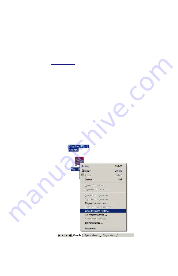
Launch RSNetworx from the computer you are using to manage your PLC. Add the
Alicat to your network tree (your scanner should add itself automatically). Then right
click on the Alicat device in your network tree and select “Class Instance Editor…”
Execute a Get Single Attribute call as shown below. Note that the instance value needs
to be in hex format (instance 101 is 16#65). The returned value is a 2 byte unsigned integer.


