


2
www.observint.com
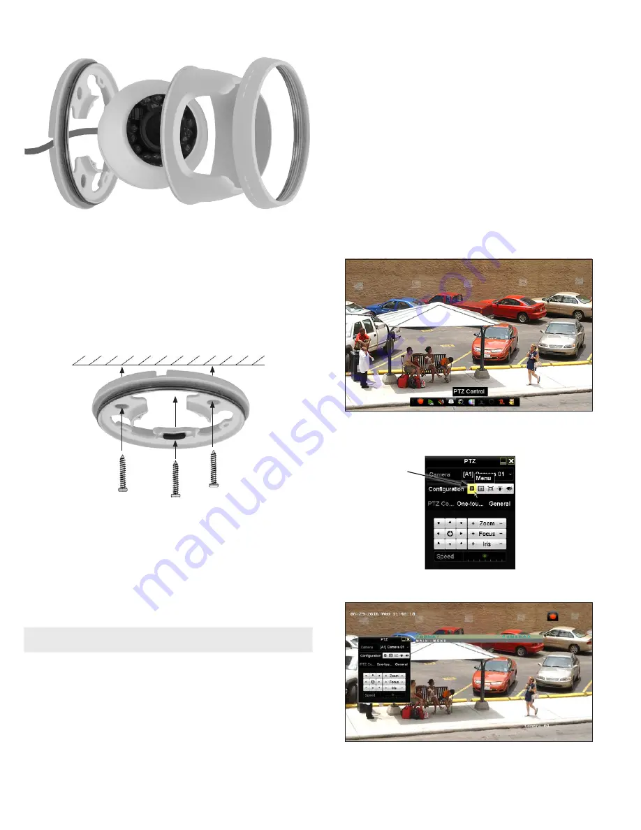
2.
Separate the housing and the camera module from the mounting base.
3.
Using the mounting template or the mounting base, mark the holes for the camera mounting
screws.
4.
Drill holes for the screws that anchor the base to the mounting surface. The mounting hardware
provided is appropriate for most surfaces. However, depending on the surface material and strength,
more appropriate fasteners may be required.
5.
Drill a 3/4” hole through the mounting surface for the drop cable, if necessary.
6.
If using wall inserts for the mounting screws, install the wall inserts at this time.
7.
Attach the mounting base the surface using the appropriate fasteners. If the camera drop cable will
route through a cable guide, lay the cable in the guide before tightening the mounting screws.
8.
If the drop cable will route through a hole in the mounting surface, route the cable through the hole,
and then reassemble the camera on the mounting base. Tighten the bezel only enough to hold the
assembly together, but do not tighten the bezel.
9.
Adjust the camera module so the orientation mark (UP) is up. See page 1 of this guide for the
location of the orientation mark.
10. Connect the camera drop cable to video and power extension cables.
11. Connect the other end of the video extension cable to a video monitoring device, such as a
compatible HD-TVI capable DVR.
NOTE
Drop cable connectors are not waterproof.
12. Connect the other end of the power extension cable to a 12 Vdc power source. Observe the polarity
of the cable shown in the photo on page 1 of this guide.
Step 2. Camera adjustments
1.
Apply power to the camera.
2.
Verify that video from the camera can be seen on a compatible HD-TVI DVR (HVR) monitor.
3.
While observing video from the camera, adjust camera direction, tilt and horizontal alignment to
point the camera at your surveillance target. Loosen the bezel if needed to so the camera module
can be adjusted easily.
4.
While holding the camera module and enclosure in place, tighten the bezel to lock the camera in
position.
Step 3. Open the OSD menu
The On Screen Display (OSD) provides configuration options for refining the performance of the camera.
It also can be used to block sensitive portions in the field of view (Privacy). You can open the OSD menu
system from either the HVR Live View display or through remote login to the ALIBI recorder.
Opening the OSD Menu through the HVR
To open the OSD menu on the HVR monitor:
1.
Open the HVR Live View screen, and then click inside the screen where the PTZ camera video image
is displayed. See below.
2.
Click the
PTZ Control
icon in the Quick Setting Toolbar. The PTZ camera Live View window will
expand to full screen and the pop-up window shown below will open.
Menu
icon
3.
In the
PTZ Control
panel pop-up window, click the
Menu
icon on the
Configuration
line.
4.
Drag the PTZ Control window to a position where it doesn’t cover the OSD menu (such as the left
side).
© 2016 Observint Technologies. All rights reserved.


