background image

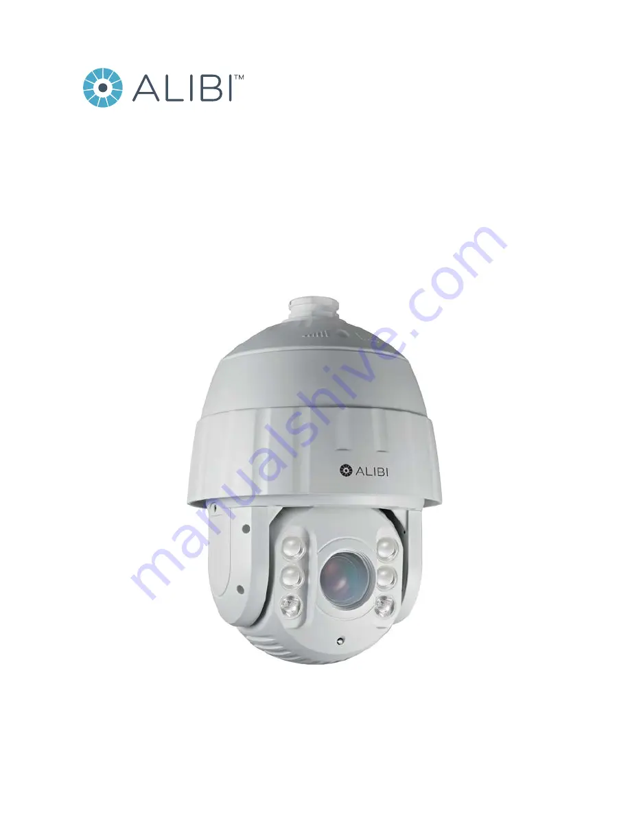
ALI-PTZ30XR 1080P HD-TVI IR  

30x Zoom Outdoor PTZ Camera  

User Manual

Products: ALI-PTZ30XR

Please read this manual before using your camera, and always follow the instructions for 
safety and proper use. Save this manual for future reference. 

ALI-PTZ30XR_CM 

6/11/15

Summary of Contents for ALI-PTZ30XR

Page 1: ...x Zoom Outdoor PTZ Camera User Manual Products ALI PTZ30XR Please read this manual before using your camera and always follow the instructions for safety and proper use Save this manual for future ref...

Page 2: ...o meet safety and performance standards with the use of specific Observint authorized accessories Observint disclaims liability associated with the use of non Observint authorized accessories The reco...

Page 3: ...tificationmarksshowingcertificationbyanagencyinyourregion Theconnectorthat plugsintotheACreceptacleonthepowersupplymustbeanIEC320 sheetC13 femaleconnector Seethefollowingwebsite for moreinformationhtt...

Page 4: ...tion however and affect the longevity of CCD Use the glove provided when opening the dome cover Do not touch the dome cover the acidic moisture on skin can erode the surface coating Please use a soft...

Page 5: ...s 18 SECTION 4 Configuring the PTZ Camera 19 4 1 OSD menu 20 4 2 Opening the OSD menu 21 4 2 1 ALIBI HVR PTZ OSD Main Menu 21 4 2 2 ALIBI HVR remote access PTZ OSD Main Menu 22 4 2 3 OSD menu navigati...

Page 6: ...Menu Reference 47 5 1 OSD menu tree 47 5 2 SYS INFO submenu 48 5 3 DOME SETTINGS submenus 48 5 3 1 ALARMS submenus 49 5 3 2 Configuring alarm parameters 50 5 3 3 AUXS submenu Auxiliary alarm output 51...

Page 7: ...Outdoor Camera User Manual TABLE OF CONTENTS 5 8 EXIT option 73 SECTION 6 Specifications 75 APPENDIX A Lightning and Surge Protection 77 APPENDIX B RS 485 Bus Connection 78 APPENDIX C 24VacWire Gauge...

Page 8: ...viii NOTES...

Page 9: ...tures 2 MP CMOS Image Sensor 1080p HD TVI Video Output 393 ft IR range 30x optical zoom 16X digital zoom Supports up the coax UTC controller Privacy Masking 3D DNR D WDR EIS 3D intelligent positioning...

Page 10: ...d area will move with pan and tilt functions and automatically adjust in size when the lens zoom changes 3D Positioning The camera can be controlled with a mouse and the PRIVATE Code protocol Clicking...

Page 11: ...according to the environment It can remove the unrealistic color casts in the image Patrol The camera provides up to 8 patrols In each patrol you can specify the scanning track by a group of user defi...

Page 12: ...unting bracket detail is shown below Model Type ALI PTZCL Ceiling Mount Bracket ALI PTZWB Wall Mount Bracket ALI PTZPM Pole Mount PTZ Bracket ALI PTZCM Corner Mount PTZ Bracket ALI PTZCL Ceiling Mount...

Page 13: ...30x Zoom PTZ IR Outdoor Camera User Manual SECTION 1 INTRODUCTION ALI PTZWB Wall Mount Bracket The Wall Mount Bracket is suitable for indoor and outdoor wall mounting 0 33 dia 4 G 1 5 6 30 7 64 2 95 3...

Page 14: ...1 INTRODUCTION ALI PTZPM Pole Mount PTZ Bracket The Pole Mount Bracket is suitable for outdoor pole mounting The straps can attach to a 2 64 5 00 diameter pole 2 68 2 68 7 64 7 64 5 63 3 94 dia G 1 5...

Page 15: ...7 HD TVI 30x Zoom PTZ IR Outdoor Camera User Manual SECTION 1 INTRODUCTION ALI PTZCM Corner Mount PTZ Bracket 7 64 6 96 G 1 5 16 52...

Page 16: ...ECTION 4 Configuring the PTZ Camera on page 19 for more information NOTE Ifyouare installingseveralRS 485networkdevices atthesametime manuallysettingtheDIPswitchesforaddressand baudrate willhelpreduce...

Page 17: ...ON OFF OFF OFF OFF OFF OFF 3 ON ON OFF OFF OFF OFF OFF OFF 4 OFF OFF ON OFF OFF OFF OFF OFF 5 ON OFF ON OFF OFF OFF OFF OFF 6 OFF ON ON OFF OFF OFF OFF OFF 7 ON ON ON OFF OFF OFF OFF OFF 8 OFF OFF OFF...

Page 18: ...illustrates camera installation with the ALI PTZWB Wall Mount Bracket Since camera installation with other bracket types is similar use this procedure as a general guide for installing the camera with...

Page 19: ...in the mounting surface between the mounting screws appropriate for the camera drop and interface cables e If the mounting bracket has a threaded end screw the bracket adapter into the bracket sprout...

Page 20: ...gh the mounting bracket and through the wall 4 Fit the coupling at the top of the camera assembly into the end of the mounting bracket or adapter and then rotate the camera clockwise about turn See th...

Page 21: ...hem to the camera power cables The cable interfaces of camera is shown below Two video outputs are provided one using HD TVI technology that must connect to an HD TVI compatible device such as a Hybri...

Page 22: ...th a DC power supply left diagram the input voltage must be no more than 12 Vdc 30 mA For AC power supply right diagram the external relay must be used to prevent damages to the camera and avoid risk...

Page 23: ...0x Zoom PTZ IR Outdoor Camera User Manual SECTION 2 INSTALLATION TypicalSystemInformationdisplay withoutbackgroundvideostream 10 Continue with the next section of this manual to setup the camera throu...

Page 24: ...ess of the camera COM FORMAT The communication settings of the RS 485 interface baud rate 4 digits data bit 1 digit and stop bit 1 digit PROTOCOL Protocol configuration for communicating with other de...

Page 25: ...through a control device such as a DVS These presets are fixed and cannot be edited To call the system defined presets remotely you can choose the preset number from the list in the PTZ control panel...

Page 26: ...reen Displays The camera supports following on screen displays Zoom Identifies the amount of magnification The format is ZXXX where XXX is the zoom amount PT Show Displays panning and tilting directio...

Page 27: ...o the defined position You can modify delete and call each preset you define Tours Tours are composed of a combination of Presets that are called automatically and sequentially For each preset called...

Page 28: ...ings 3 Privacys Privacy Blanks Set Blank Presets Clear Patrols Edit Patrol Preview Clear Patrol Alarms Pattern Edit Pattern Preview Clear Pattern Setting stops Clear stops AUXS Video Set Edit Zone Cle...

Page 29: ...itor 1 Open the HVR Live View screen and then click inside the screen where the PTZ camera video image is displayed See below 1 Click the PTZ Control icon in the Quick Setting Toolbar The PTZ camera L...

Page 30: ...ower right corner NOTE ThePTZ Controlwindowdirectionbuttons andtheIris andIris keysareusedtonavigatetheOSDmenuandset configurationoptionsinthecamera 4 2 2 ALIBI HVR remote access PTZ OSD Main Menu To...

Page 31: ...PTZ control panel Preset95 Call icon NOTE ThePTZ controlpaneldirectionbuttonsandtheIris andIris keysareusedtonavigatetheOSDmenuandset configurationoptionsinthecamera 4 2 3 OSD menu navigation For the...

Page 32: ...parameter set parameter value or open sub menu Iris CLOSE Cancel change of parameter p q t u can move the position in the menu up to parameter above or previous parameter value down left to next scree...

Page 33: ...the next page Click t or Iris OPEN to move to the previous page Select parameter value with p or q keys Click Iris OPEN to select the parameter value and return to mode Menu operations via the IE brow...

Page 34: ...turn the page up or down To change the value of a parameter 1 Move the cursor to the target item and then click IRIS The cursor will change to a hollow diamond 2 Click the p and q direction buttons in...

Page 35: ...icon will change to a 3 Use the p and q buttons to show the parameter to what you prefer 4 Click Iris again to change the parameter The position icon will change to a 5 Repeat steps 1 through 4 above...

Page 36: ...focus distance You can configure the focus limit to a longer distance when the target is at a distance to prevent the camera from focusing on the objects close to it or configure the focus limit to a...

Page 37: ...he current color temperature INDOOR OUTDOOR These modes are for indoor use and outdoor use respectively SELFDEF In SELFDEF you can adjust the color temperature the RED and BLUE values manually ATW In...

Page 38: ...he OSD MAIN MENUS DOME SETTINGS menu 2 Click Iris to change the BLANK NUM field 3 Use the p and q buttons to change the number shown for the blank number Blanks can be numbered from 1 8 4 Click IRIS t...

Page 39: ...ing the system time and display options and an additional screen for setting the ZERO ANGLE To configure these settings 1 Open the SYS INFO SETTINGS submenu from the OSD MAIN MENUS DOME SETTINGS menu...

Page 40: ...ature PRESET DFOCUS direct focus You can set the preset direct focus function to ON or OFF PROTOCOL You can set this option to AUTO MATCH PELCO P PELCO D Private code etc PROTOCOL C PELCO COAXITRON Us...

Page 41: ...ral system parameters on the live view display You can enable or disable the on screen display of PTZ movements alarms time presets zone address error rate and fan heat show etc When PT SHOW is set to...

Page 42: ...DOME SPEED Dome speed sets the manual movement speed of the camera Dome speed is adjustable from 1 10 IMAGE FREEZE This feature enables the live view to switch directly from one scene defined by a pre...

Page 43: ...hange to a 7 Repeat steps 2 through 6 above to change the settings of other parameters If you opened SETTING STOPS you can configure the scan range limits left up right and down To set stops 1 Use the...

Page 44: ...direction After a preset is defined you can click the calling button for that preset to move the camera to that direction There is no preset menu in the OSD You can set presets with the PTZ panel of t...

Page 45: ...2 Call a preset Through a web browser connected to your DVR select the preset number from the preset list in the control panel of the DVR then click the icon to call the preset 4 8 3 Clear a preset 1...

Page 46: ...the u buttons to move the position icon to the PST preset field 7 Use the p and q buttons to select the first preset of the patrol This will be the first surveillance target the camera points at when...

Page 47: ...to preview and then click Iris 3 Move the position icon to the PREVIEW option and then click Iris The patrol you selected will play indefinitely 4 Click Iris again to stop the preview and return to t...

Page 48: ...1 Open the PATTERNS submenu from the OSD MAIN MENUS DOME SETTINGS menu NOTE REMAINMEMORY indicatestheremainingmemoryofthecamerafor configuringpatterns When itreaches0 no more patterns canbe configure...

Page 49: ...Use the p and q buttons to select the number of the pattern you want to preview and then click Iris 3 Move the position icon to the PREVIEW option and then click Iris The pattern you selected will pl...

Page 50: ...tions include preset 1 8 pattern 1 4 patrol 1 4 pan scan tilt scan random scan frame scan panorama scan day night mode or none 4 11 1 Create a Time Task 1 Open the TIME TASK submenu from the OSD MAIN...

Page 51: ...button to move the cursor to the START Minutes field and then use the p and q buttons to choose the minute when the task will start Options are 00 59 12 Repeat the two previous steps to set the END H...

Page 52: ...riggered by a closed circuit between the alarm input and alarm ground CLOSE If you set the status as CLOSE alarm will be triggered by open circuit between the alarm input and alarm ground OFF If you s...

Page 53: ...ty occurs at the same time the camera will respond to one alarm first and then respond to the next one after the user defined interval You can set the on ALARM SEQUENCE submenu from 1 to 200 seconds 3...

Page 54: ...auxiliary outputs You can set the alarm output type as OPEN normally open and CLOSE normally closed 3 Move the cursor to DWELL TIME to set the duration of the auxiliary output signal The configurable...

Page 55: ...ure of the on screen display OSD is shown below MAIN MENU Page 1 Page 2 Sys Info Settings 1 Sys Info Settings 2 Sys Time Display Settings Sys Info Settings 3 Privacys Privacy Blanks Set Blank Presets...

Page 56: ...RS 485 communications settings are in the format baud rate data bits stop bits Temperature is shown in Celsius 2 To view the second SYS INFO display click the u button in the PTZ control panel To ret...

Page 57: ...e item and then click Iris A description of the DOME SETTING submenus are included below 5 3 1 ALARMS submenus You can configure the camera to respond to alarm events with alarm linked actions such as...

Page 58: ...u can set the alarm action as preset from 1 to 8 pattern from 1 to 4 patrol from 1 to 8 panning scan tilting scan random scan frame scan panoramic scan day mode night mode or none You can also set the...

Page 59: ...e the dome activity You can set ALARM RESUME to ON to enable the camera to resume its previous activity after the triggered actions finished NOTE Ifthecamera ismoving whena linkageaction istriggered i...

Page 60: ...oose 1 to activate AUX 1 or choose 2 to activate AUX 2 5 3 4 CAMERA PARAMETER submenus The CAMERA PARAMETER submenu include five pages each with no additional submenu To open the CAMERA PARAMETERS sub...

Page 61: ...w lighting environment Higher setting values produce stronger chroma suppressing effects CONTRAST adjust the image contrast on CONTRAST submenu between 0 and 7 D N LEVEL The D N level is the switching...

Page 62: ...ou can set the SHARPNESS level from 0 to 15 SHUTTER speed If you set the SHUTTER value larger the shutter speed is faster The value indicates the inverse of the shutter speed 1 value seconds At faster...

Page 63: ...panning loss tilting loss and communication loss Panning loss and tilting loss refer to the failures of panning and tilting for diagnosing the electric motor of the camera To clear a group of PTZ sett...

Page 64: ...STOPs The camera can be programmed to move within the configurable limit stops left right up down PARK ACTion The action the camera will automatically perform after a pre defined period PARK TIME of...

Page 65: ...the settings of other parameters If you opened SETTING STOPS you can configure the scan range limits left up right and down To set stops 1 Use the p and q buttons to move the position icon to the SET...

Page 66: ...part of a patrol must be created You can create up to 10 patrols and then invoke both automatically or manually as needed To create a patrol 1 Open the PATROL submenu from the OSD MAIN MENUS DOME SETT...

Page 67: ...k the u buttons to move the position icon to the SPD speed field and then use the p and q buttons to select the relative speed at which the camera moves to the preset Values for the SPD field can be 1...

Page 68: ...Open a web browser and log into the DVR connected to your PTZ camera 2 Open the live view display of the camera 3 In the PTZ control panel select the system defined preset number corresponding to the...

Page 69: ...the pattern number Patterns can be numbered from 1 5 4 Click IRIS to save the pattern 5 Use the p and q buttons to move the position icon to the EDIT PATTERN option and then click Iris to open the edi...

Page 70: ...o delete the pattern Call a pattern You can call some patrols Pattern 1 5 using system defined presets To do that 1 Open a web browser and log into the DVR connected to your PTZ camera 2 Open the live...

Page 71: ...at your preset target then click Iris to save the preset and return to the PRESETS menu 7 Repeat steps 2 through 6 above to create additional presets 8 To clear a preset a Open the PRESETS menu and t...

Page 72: ...S to create the blank 5 Move the position icon to the SET BLANK option and then click Iris The POS position adjustment screen will open 6 Use the t u p and q buttons to position the blank box over the...

Page 73: ...or OFF FAN CONTROL You can set the internal FAN CONTROL to TEMP ON or OFF When FAN CONTROL is set to TEMP the fan is controlled by the temperature PRESET DFOCUS direct focus You can set the preset dir...

Page 74: ...ow 2 Use the p and q buttons to show the parameter to what you prefer 3 Click Iris again to change the parameter The position icon will change to either a or 4 Repeat steps 1 through 3 above to change...

Page 75: ...m parameters on the live view display You can enable or disable the on screen display of PTZ movements alarms time presets zone address error rate and fan heat show etc When PT SHOW is set to ON the c...

Page 76: ...DISPLAY SETTINGS page 2 and the repeat steps 1 through 3 above to change other parameters as needed 5 3 12 TIME TASK submenu A time task is a pre configured action that can be performed automatically...

Page 77: ...choose when during the week the task will be executed Options include WHOLE WEEK SUNDAY MONDAY TUESDAY WEDNESDAY THURSDAY FRIDAY and SATURDAY 10 Next click the u button to move the cursor to the STAR...

Page 78: ...ons to show the frame rate you prefer and then click Iris again to confirm the setting 5 3 14 ZONES submenu ZONE submenu is used to divide a scene into different parts You can define labels that are d...

Page 79: ...t extreme of the zone you are configuring and then click Iris to save the settings and return to the ZONES menu NOTE Afterthezoneisdefined theZONESTATUSchangesfromOFFtoON Thisstatusisnotdirectlyconfig...

Page 80: ...ay settings This function is useful when the live image is not clear due to changes of the camera configuration settings 1 Use the p and q buttons to move the position icon to RESTORE CAMERA 2 Click I...

Page 81: ...ge The default language is ENGLISH To change the OSD language 1 Use the p and q buttons to move the position icon to LANGUAGE and then click Iris The position icon will change to a 2 Use the p or q bu...

Page 82: ...74 SECTION 5 OSD MENU REFERENCE...

Page 83: ...r Time 1 1 10 000 s Day Night IR Cut Filter Digital Zoom 16x Privacy Mask 8 privacy masks programmable a maximum of 8 zones can be masked simultaneously on the same video screen Focus Model Auto Semia...

Page 84: ...omposite BNC RS 485 Interface Half duplex mode Self adaptive COAXITRON Pelco P Pelco D protocoL UTC function COAXITRON or ALI UTC controller General Menu Language English Chinese Alarm input 2 normall...

Page 85: ...bstation high power lightning protection apparatus and lightning conductor are necessary The design for installation and wiring with lightning protection and grounding should be combined with the ligh...

Page 86: ...ion with 24 AWG wire Baud rate Maximum distance 2400 bps 5900 ft 1800 m 4800 bps 3900 ft 1200 m 9600 bps 2600 ft 800 m The transmission distance is decreased for thinner cable when the wire is exposed...

Page 87: ...uch as signal reflection uncontrollable or self running cameras and anti jamming inability with devices that are far away In the star shaped connection the termination resistors are usually placed in...

Page 88: ...ress and baud rate to match in the controller and the camera RS 485 are connected incorrectly Correct the RS 485 wiring connections Wiring is disconnected Fastening the wire RS 485 wire is broken Chan...

Page 89: ...gauge required is 0 8000 mm Table 5 Table of wire gauge standards Distance ft m Wire Gauge mm Power VA 0 8000 1 000 1 250 2 000 10 283 86 451 137 716 218 1811 551 20 141 42 225 68 358 109 905 275 30...

Page 90: ...ANCE Table 6 Wire Gauge Standards Bare Wire Gauge mm American Wire Gauge AWG Cross sectional Area of Bare Wire mm2 0 750 21 0 4417 0 800 20 0 5027 0 900 19 0 6362 1 000 18 0 7854 1 250 16 1 2266 1 500...

Reviews: