


2
www.observint.com
Step 2. Install the camera
The camera includes hardware to install it directly to the Junction box provided (preferred), to a mounting
surface (without the junction box), or to a 2-gang electrical box using the adapter plate provided. When
using the junction box, camera drop cables can attach to extension cables (for LAN, power, etc.) inside the
box. The camera with or without the junction box can be installed on a ceiling (horizontal surface) or wall
(vertical surface). To install the camera, do the following:
To mount the camera using the Junction box
1.
Determine the best fasteners for securing the Junction box to mounting surface. The mounting
hardware provided is suitable for most surfaces.
2.
Remove the junction box from the camera assembly by loosing the four captive screws.
3.
Using the Junction box as a template, mark the location of the Junction box mounting screw holes. If
routing extension cables for the LAN, power, alarm devices, etc. through the mounting surface, mark
the location for that hole too. If installing the box onto a vertical surface, observe the orientation for
TOP and BOTTOM orientation markings inside the box.
Mounting surface
Orientation
markings
Junction box
Mounting screws (4)
4.
Drill holes in the mounting surface for the mounting screws and extension cables (if necessary).
5.
Secure the Junction box to the mounting surface using appropriate fasteners.
6.
Route the network LAN, power, ALARM, RS485, and AUDIO extension cables between the junction
box and the devices they connect to. Do not apply power to the extension cables at this time.
7.
Attach the camera safety cable to the safety hook inside the junction box.
Camera to junction box
mounting screws (4)
Safety cable
Safety cable hook
Camera
To mount the camera onto a surface without the junction box
For this mounting option, the drop cables must be stored behind the mounting surface.
1.
Determine the best fasteners for securing the camera mounting base to mounting surface. The
mounting hardware provided may be suitable for some surfaces.
2.
Remove the junction box from the camera assembly by loosing the four mounting base captive
screws.
3.
Remove the four mounting base captive screws.
4.
Using the camera mounting base as a template, mark the locations of the holes for the mounting
screws. Also mark the location of a hole for the camera drop cables.
5.
Route extension cables from the power source and LAN switch (or LAN with PoE), and peripheral
devices for the left (or microphone) and right audio channels, and alarm input and output devices to
the mounting location.
To mount the camera onto an electrical box
1.
Install a double-gang electrical box at the location where the camera will be installed.
2.
Attach the adapter plate provided to the electrical box using four (4) screws.
3.
Remove the junction box from the camera assembly by loosing the four mounting base captive
screws.
4.
Attach the junction box to the adapter plate using four (4) screws.
5.
Route extension cables from the power source and LAN switch (or LAN with PoE), and peripheral
devices for the left (or microphone) and right audio channels, and alarm input and output devices
into the electrical box, and then up through the cable opening in the adapter plate and junction box.
6.
Attach the camera safety cable to the safety cable hook inside the junction box.
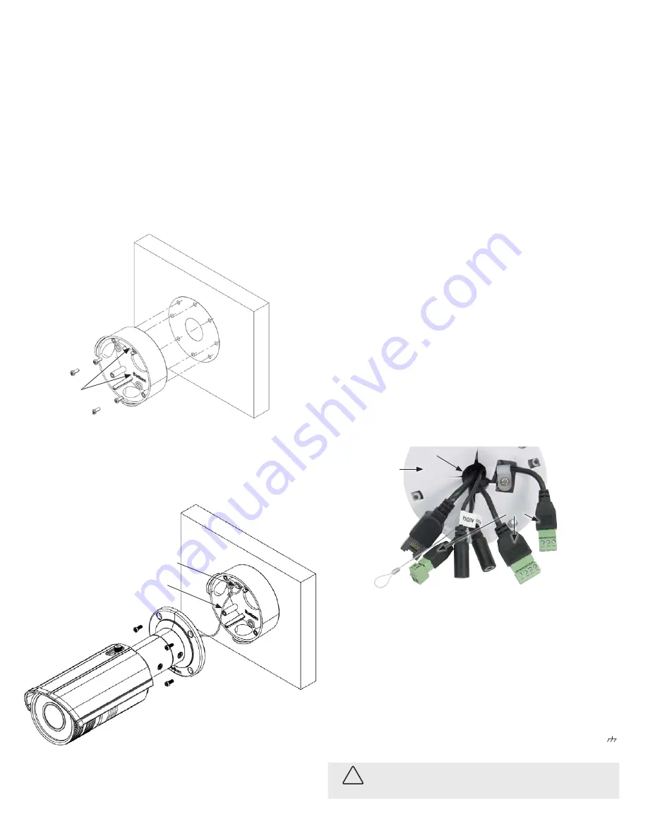
Step 3. Connect camera drop cables to peripherals, LAN and
power
Ethernet connector
(PoE capable)
Camera
mounting
base
Cable access
Alarm IN/OUT
Terminals
labels
12 Vdc
Power
connector
Audio IN/OUT
RS485 (D-, D+)
Safety cable
Camera drop cables to Ethernet, power and peripheral devices
1.
Connect the network ALARM, RS485 and AUDIO extension cables to the camera drop cables as
needed. The camera can connect to an alarm input sensor and an alarm output (reporting) device,
and to one microphone and one audio line out device. The camera can also connect to an RS485
network for control of the lens. Labels on the alarm and RS485 drop cables show where to connect
the extension cable wires.
2.
Connect the Ethernet LAN cable to the camera LAN drop cable. Protect the connection from
moisture and other contamination, if necessary. A weatherproof fitting is provided. Instructions for
using the weatherproof fitting are provided on the web page for the product.
3.
If the camera is not powered using PoE (Power over Ethernet injector), connect the 12 Vdc power
extension cable to the 12 Vdc power drop cable. The power drop cable terminals are labeled
+
,
, and
-
.
CAUTION
Do not apply power to the camera at this time. Before applying power to the camera, ensure that
the polarity is correct. An incorrect connection may cause a malfunction and can damage the
camera.
© 2014, 2015 Observint Technologies. All rights reserved.


