


Before proceeding with installation, please follow these instructions carefully:
1) Check that the pipes to be connected to the valve are aligned in order to avoid
mechanical stress on the threaded joints.
2) Check that the DUAL BLOCK® union nut locking device (16) is installed on the
valve body.
3) To release the union nuts (13), axially press the release lever to separate the lock
and then unscrew it in the counter-clockwise direction.
4) Unscrew the union nuts (13) and insert them on the pipe segments.
5) Solvent weld or screw the end connectors (12) onto the pipe ends.
6) Position the valve between the end connectors making sure the that direction
of flow is the same as shown by the arrow on the plate. Hand tighten the union
nuts (13) in the clockwise direction. Do not use a wrench or other tools which might
damage the surface.
7) Lock the union nuts by returning the DUAL BLOCK® to its housing, pressing on it
until the hinges lock on the nuts.
8) If necessary, support the pipework with FIP pipe clips or by means of the carrier
built into the valve itself (see paragraph “fastening and supporting”).
Seals can be adjusted using the insert (1).
The seals can be adjusted later with the valve installed on the pipe by simply
tightening the union nuts. This "micro adjustment", only possible with FIP valves
thanks to the patented "Seat stop system", allows the seal to be recovered where
PTFE ball seats are worn due to a high number of operations.
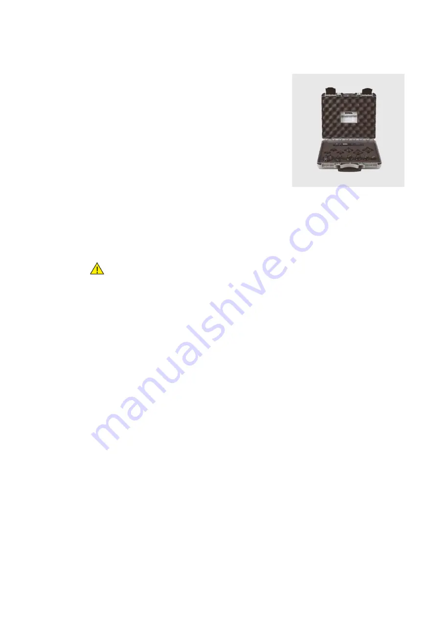
The Easytorque kit can also be used for micro adjustments (fig. 3).
WARNINGS
- Always avoid sudden closing manoeuvres and protect the valve from accidental
operations.
Fig. 3
223
InstaLLatIon