


DISASSEMBLY
1) Isolate the valve from the line (release the pressure and empty the pipeline).
2) Disconnect the actuator from the power mains.
3) Remove the two screws (22) and lift the actuator (24) with the upper plate (17).
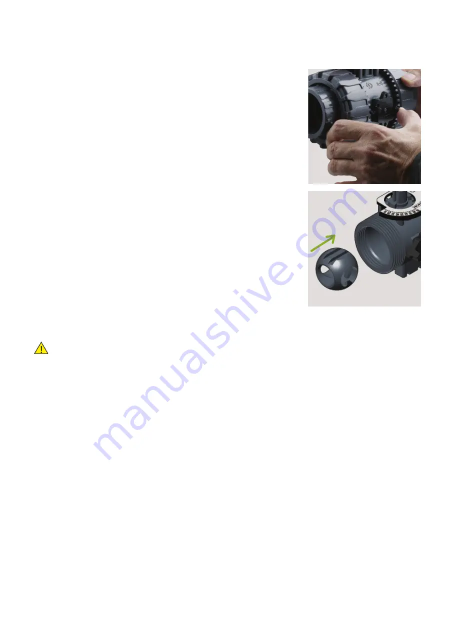
4) Release the union nuts by pressing the lever on the DUAL BLOCK® (16) along the axis and
separate it from the union nut (fig. 1). It is also possible to completely remove the locking
device from the valve body.
5) Fully unscrew the union nuts (13) and extract the body sideways.
6) Before dismantling, hold the valve in a vertical position and open it 45° to drain any liquid
that might remain.
7) After closing the valve, remove the special insert (1) and push the two projecting ends
into the corresponding recesses on the ball seat carrier (11), turning counter-clockwise to
extract it.
8) Press on the ball from the side opposite the "REGULAR - ADJUST" label, being sure not to
scratch it, until the ball seat carrier exits (11), then extract the ball (6).
9) Extract the connection module (19) by pulling up.
10) Press the stem (4) inwards until it exits the body.
11) All the O-rings (3, 8, 9, 10) and PTFE ball seats (5) must be removed from their grooves, as
shown in the exploded view.
ASSEMBLY
1) All the O-rings (3, 8, 9, 10) must be inserted in their grooves as shown in the exploded view.
2) Insert the stem (4) from inside the valve body (7).
3) Place the PTFE ball seats (5) in the housings in the body (7) and in the ball seat carrier (11).
4) lnsert the ball (6) in the body as shown in fig. 2.
5) Screw the support (11) into the body and tighten up in the clockwise direction using the
special insert (1) housed in the handle.
6) If previously removed, reassemble the DUAL BLOCK® system (16) on the valve body.
7) lnsert the valve between the end connectors (12) making sure that they match the direction
of flow shown by the arrow on the plate, then tighten the union nuts (13) making sure that
the socket O-rings (10) do not come out of their grooves.
8) Insert the connection module (19) on the stem (4).
9) Reassemble the actuator (24) with plate (17) on the valve making sure the ball position (6)
and actuator stem are aligned.
10) Tighten the two screws (22) and reconnect the actuator to the power supply.
All operations on equipment under pressure or containing compressed springs must be
carried out under safe conditions for the operator.
Note:
: during mounting operations, it is advisable to lubricate the rubber seals. Mineral oils
are not recommended for this task as they react aggressively with EPDM rubber.
The photos refer to the manual version and are purely exemplary.
Fig. 1
Fig. 2
222