3 Installation
Study the instructions carefully.
The valve is supplied as separate parts to facilitate welding. The items refer to the Parts list and service kits section.
Check the valve for smooth operation after welding. Man = Manually open and close, NC = Normally closed.
3.3
Welding
Step 1
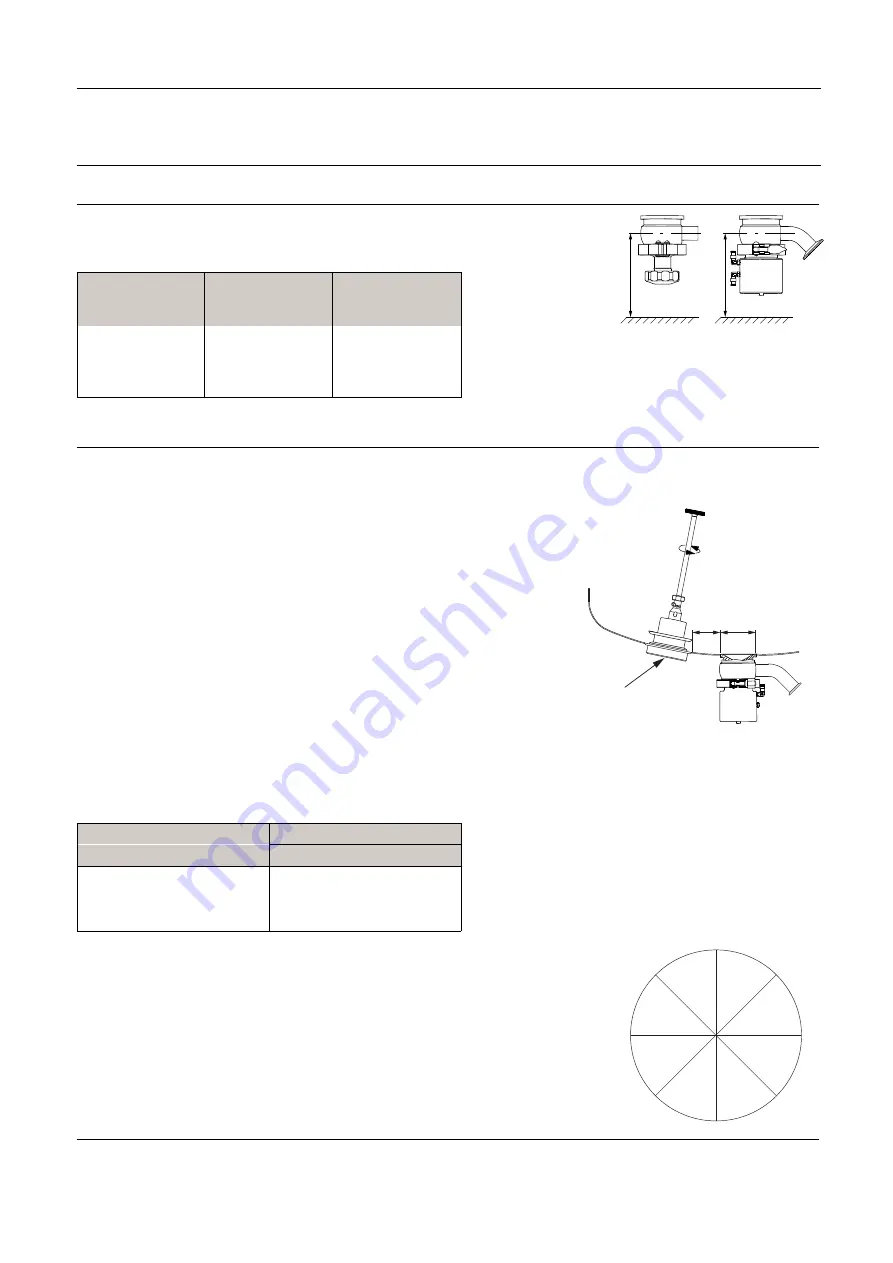
Always weld the valve so that the actuator with the internal parts
can be removed.
Valve size
DN/OD
A mm (inch)
Air actuator
B mm (inch)
Manual actuator
12.7 mm (½ inch)
132 mm (5.2 inch)
92 mm (3.6 inch)
25 mm (1 inch)
168 mm (6.6 inch)
98 mm (3.9 inch)
38 mm (1½ inch)
182 mm (7.1 inch)
112 mm (4.4 inch)
NOTE! If there is a risk of foot damage, Alfa Laval recommends to
leave a distance of 120 mm (4.7”) below the actuator.
2508-0057
A
B
Step 2
Placement of the tank outlet valve
The valve housing is usually placed according to the figure
below, but other locations may exist
2508-0058
øC
A
e.g. Weldplate mixer
A = Min. distance between the weld in components, in
accordance with the PED.
Diameter of weld flange (hole)
Valve size
øC
12.7 mm / ½ inch
ø50 mm / 1.97 inch
25 mm / 1 inch
ø79 mm / 3.11 inch
38 mm / 1½ inch
ø85 mm / 3.35 inch
A hole (see table) for the valve is cut in the tank plate.
Grind the edge so there is no gap between valve and tank plate.
Only use pulsed arc welding (low heat input) to avoid deforming the valve body.
Tack weld always on the opposite side (8 segments with filler metal).
Weld root if possible without filler metal.
Welding of the final run must be done in 8 segments to avoid cracking.
The inside and outside of the weld is ground and polished to the required finish.
TD 449-244
4
8
5
1
2
6
7
3
10
Summary of Contents for UltraPure Series
Page 2: ......


