


29
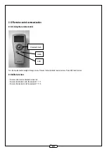
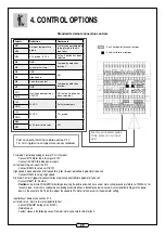
4. CONTROL OPTIONS
Standard terminal connection controls
Labels
Defi nition
Comments
M17
Air input temperature
probe
Factory connected probe
to be placed in the air
input duct
M16
M12
CO
2
probe - 0-10 V
Active if option has been
selected
M4
GND
Jumped by default on
terminal
M5
unit external stop
M4
GND
NO
M3
High speed
M8
Fire Alarm contact
Jumped by default on
terminal
M7
GND
RG1
Insulation damper relay -
ON/OFF
NO (active if option has
been selected)
RG2
+24
24V AC
Actuator dampers
GND
+24
24V AC
CO
2
probe
GND
M36
unit Alarm return relay
NO
M37
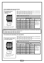
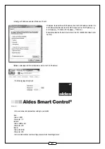
CO
2
probe: Control depending on level of CO
2
in the room.
- Connect M12-M4 for the return signal 0-10 V.
- C24/GND for probe power supply.
unit external stop: set-up unit On/Off.
- Connect M5-M4 to set-up unit On/Off.
High speed : Forced operation at full speed for a given time period (software parameter to be set).
- Connect M4-M3 to set-up High speed.
Fire Alarm Contact: triggers forced ventilation at a given speed (software parameter to be set).
- Connect M8-M7 for fi re alarm.
-
Caution:
under Article CH38 (ERP) for buildings receiving the public and which have one or more units processing in total over 10000m
3
/h for
the same room or which are used solely as sleeping accommodation: a standalone external sensor must automatically trigger a fan power
down in the event of a fi re. To do this, adjust the speed to 0%. Refer to the manual for the parameter setting.
Input/exhaust damper: see section 2.7.3.
unit Alarm return: alarm return relay (potentially free).
- Connect M36-M37 (voltage max. 24VAC).
- Normally open.
- Contact closes in the following cases: fi re alarm/water coil pump fault/motor fault.
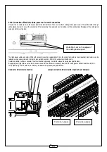
Fast connector terminal-cable section 0.14
1.5 mm2-rigid wire crimped wire recommended
Factory connected probe
To be placed in air input
duct
2 or 3 horizontal terminal jumper
2 vertical terminal jumper