Alde Comfort 2923 Service Manual Download Page 12

1

1

1

1

Fig 17

Fig 18

+

_

A

Fig 0

Fig 19

A

B

:  ADjuStIng thE BOIlER tEmPERAtuRE

1.

  Remove the hatch on the control panel by opening it 

straight out and carefully bending it in the middle so that 
the pegs are released (se Chapter 6:12). 

.

  Remove the lower front plate (see fig 12).

.

  Switch off the main power switch, set the thermostat 

knob in position 2, so that the hole with the figure 5 
on the automatic unit knob is straight ahead. Unfasten 
the screws (fig 17 A) on both sides of the plastic con

-

ductor on the rod. Push the rod and knob to the side. 
Remove the white plastic plug, press down the nozzle 
and remove the screw with a 7 mm spanner, (with serial 
numbers from 21425, a special tool is required for remo

-

ving the screw.) Remove knob and spring (see fig 17).

.


temperature adjustment: 

Note the scale on the edge 

of the plastic wheel (corresponds to the scale on the 

knob) and the index on the cover. Lift the plastic wheel 
approximately 10 mm (see fig 18). Turn anti-clockwise 
to reduce the temperature and clockwise to increase it. 
Carefully push the plastic wheel down so that the teeth 
engage, every tooth movement is equivalent to approx. 
3°C change in temperature. 

.

  Fit the spring, knob and screw. Turn the knob to the stop 

position, switch on the main switch/insert fuse. Start and 

test-run the boiler at max temp (knob in position 7) with 

the circulation pump switched off. Check that the boiler 
switches off (main burner goes out) at the correctly set 
system temperature. If necessary, make further adjust

-

ments.

Basic setting of temperature: 

With the sensor in a water 

bath, temperature 70°C, turn the thermostat knob from 
position 7 towards 1, switching, ”ticking” occurs between 
positions 6½ - 4½. On burner unit with serial numbers > 
28798, the water bath must be at 65°C. 

.

  Press in the plastic plug, fit the rod with the plastic adap

-

ted, (NOTE! The figure 5 must be visible in the hole). 
Turn to the stop position, check that the spark shuts off 
and that the lamp stops flashing.

7.

  Fit the lower front plate (see fig 12). Install and close the 

hatch.

6:3  RePLACING tHe oveRHeAtING  


PROtECtIOn 

1.

  Remove the lower front plate (see fig 12). 

.

  Unfasten the springs (fig 13 A) which hold the sensor (fig 

13 B) and overheating protection (fig 13 C) to the boiler 
casing.

.

  Unwind the sensor from the overheating protection.

.

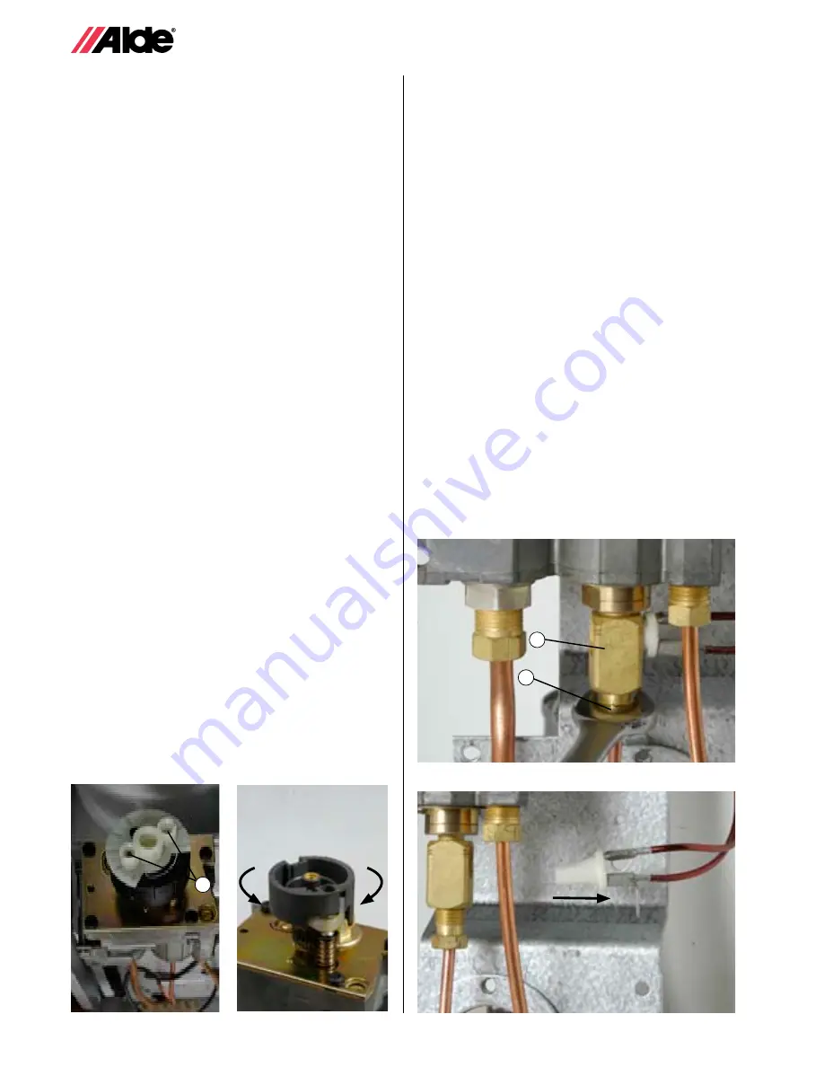
  Slacken the nuts on the thermo-element (fig 19 A) a 

couple of turns in the joint nipple (fig 19 B) below the 

automatic unit and then pull the overheating protection 

straight out of the joint nipple (see fig 20). Check that 
the joint metal is free from oxidation, if necessary clean 
or replace it.

.

  Fit the new overheating protection into the joint nipple. 

Tighten the nuts from the thermo element, but not too 
much. Check that the cables for the overheating protec

-

tion are not lying against the gas pipe. 

.

  Wind the sensor wire round the new overheating protec-

tion and attach the sensor with spring in the recess in 

the boiler casing. Check that there is heat - conducting 
paste on the sensor. 

7.

  Tilt the overheating protection at the top and push it 

down into the holder. Attach it with the spring. 

8.

  Start the boiler in accordance with instructions. Check 

that the boiler continues to burn when the thermostat 

knob is released. Fit the lower front plate (see fig 12)

Summary of Contents for Comfort 2923

Page 1: ...SE GB Servicemanual Comfort 2923 2928 ...

Page 2: ... The handbook may also be of assistance in ordering spare parts in understanding how the boilers operate and how they are installed It also includes general information on how our heating systems are designed and some information on LPG and LPG installations We hope that you will find this manual very useful and that it will save you time during service and fault finding on our boilers Alde Intern...

Page 3: ...th liquid Ensure that the caravan or boat is level and check that the air screws and drainage tap are closed Remove the upper front plate on the boiler Then slacken the plastic cap on the circulation pump and lift up the pump Then carefully pour the glycol mix into the expansion chamber When the system is being filled air pockets may form depending on how the pipe system was installed A good indic...

Page 4: ... with a characteristic smell is added it smells like sulphur It can be stored in the cylinder for an unlimited time without any deterioration in quality LPG is non toxic but if bottled in concentrated form it will give rise to some anaesthetic effects breathing difficulties and symptoms of suffocation and therefore may be avoided The LPG cylinder contains LPG both in liquid and in gas form When th...

Page 5: ...t demands heat the circula tion pump starts The liquid in the system then begins to circulate and cold water enters the boiler A sensor fitted in the water jacket senses that the water is colder than the temperature set on the boiler thermostat The pilot light ignites the main burner which heats up the liquid and circu lates it round the system When the warmth in the caravan reaches the temperatur...

Page 6: ... thermostat Switch N K Switch 12 230 V 12 V Circula tion pump Relay on el cartridge for 230 V circ pump 12 V Fuse ON OFF Room thermostat Switch N Switch 1 kW 2 kW 1050 W 1050 W 0 Circuit board on el cartridge 4 0 Flow chart LPG Boiler Circulation pump Output electrical cartridge ...

Page 7: ... hub wipe any excess away If the knob feels springy does not remain in the position in which it is released lubricate the o ring very sparingly with grease Replace the thermostat knob NOTE When the thermostat knob is removed it must be re fitted in the same position otherwise the temperatures setting will change 5 1 General fault finding This guide to general fault finding should be useful in rapi...

Page 8: ... 6 The pilot burner must burn with a clear blue flame without yellow peaks Check that the tip of the thermo element is in the centre of the pilot flame Adjust if necessary by carefully bending the bracket Check and if necessary clean the contact surfaces in the joint nipple between the thermo element the over heating protection and the magnetic insert in the automa tic unit and that the nuts on th...

Page 9: ...medial action Check in the expansion chamber that the heating system is filled to the correct level with 40 glycol mix Check that the sensor is attached with heat conducting paste between the boiler and the sensor and that the capillary tube is not damaged Turn the thermostat knob to position 1 and check that the main flame goes out and if it does lower the max temp setting If the flame does not g...

Page 10: ...cts 5 14 Circulation pump does not start Cause No voltage to boiler Switch on room thermostat off Temperatures setting too low room thermostat has trip ped Room thermostat wrongly calibrated or faulty Switch for circulation pump on control panel in wrong position faulty Cable connections not attached to motor Pump motor faulty Remedial action Check voltage and fuse Check that the switch on the roo...

Page 11: ...e boiler see fig 16 8 Check that the front packing fig 16 A is intact before the burner unit is replaced Fasten the burner unit and earth cable Attach the inlet gas pipe to the burner unit and tighten Install the overheating protection sensor and ignition cable Ensure that there is heat conducting paste between the sensor and the boiler Check that the capillary tube to the boiler thermostat overhe...

Page 12: ... temperature With the sensor in a water bath temperature 70 C turn the thermostat knob from position 7 towards 1 switching ticking occurs between positions 6 4 On burner unit with serial numbers 28798 the water bath must be at 65 C 6 Press in the plastic plug fit the rod with the plastic adap ted NOTE The figure 5 must be visible in the hole Turn to the stop position check that the spark shuts off...

Page 13: ...t fig 19 A from the joint nipple fig 19 B below the automatic unit and pull out the thermo ele ment through the cable opening on the front plate of the burner unit 4 Check the contact surfaces on the joint nipple and the overheating protection clean or replace joint nipple if necessary 5 Install the new thermo element in reverse order NOTE The tip of the thermo element must be pres sed up as far a...

Page 14: ...te of the burner unit 3 Fit the new ignition cable and connect it to the spark plug and ignition transformer Don t firget the silicone sleeve 4 Push the burner unit into the boiler and install it in accor dance with Chapter 6 1 Check that the capillary tube to the boiler thermostat the temperature limiter and the ignition cable are correctly aligned to the right of the automatic unit and are not t...

Page 15: ... inner screw on the micro switch fig 27 A a couple of turns adjustment screw remove the outer screw fig 27 B Removed the micro switch note the location of the cables move cables and adjustments screws to the new switch fit and tighten the screws 5 Fit the rod in the automatic knob and replace the screw 6 Adjustment Set the thermostat knob in the ignition position Slacken the adjustment screw and p...

Page 16: ...e top cover of the boiler Switch on the main power switch turn the ther mostat knob to the ignition position and check that the indicator lamp flashes and that there are sparks at the spark plug If necessary adjust the micro switch Carry out a complete functional check on the control panel to ensure that all functions are OK Test start the boiler and check that the thermostat knob can rotate freel...

Page 17: ...35 B inwards 6 Transfer the ignition transformer to the new control box note the location of the cables fit the cables 7 Fit the connection block and the earthed connections in the top cover earth cable on the burner unit the cables to the 12 V circulation pump as well as the connection block to the electrical cartridge 8 Install the control box by pressing it into the metal sweep of the boiler un...

Page 18: ...on the connection pipe before the vessel is fastened properly Then pressed the new expansion vessel down on to the pipe bend and tighten the nut fig 38 B a few turns Attach the support fig 37 A and then tighten the nut Fit the hoses 9 Close the drainage tap and top up the liquid in the expansion vessel Lower the circulation pump into the vessel and screw on the plastic nut fig 36 B Attach the pump...

Page 19: ...Red Black Fuse 1 A Red Black _ 12 V DC Battery Room thermostat Yellow P Red White N K 12 220 Pump Blue Grey Red 275 ohm 275 ohm 275 ohm 230 pump 1000 W 1000 W Electrical cartridge N 1000 W 2000 W Red Yellow Black K Black Ignition transformer Micro switch Green Yellow L _ ...

Page 20: ...20 20 8 0 Exploded view 2923 1 2 3 4 5 6 7 8 9 10 11 12 13 14 15 16 17 18 19 20 21 22 23 24 25 26 27 28 29 30 31 32 33 34 35 36 37 38 39 ...

Page 21: ...21 21 9 0 Exploded view 2928 1 2 3 4 5 6 7 8 9 10 11 12 13 14 15 16 17 18 19 20 21 22 23 25 26 27 28 29 31 31 33 34 35 36 30 41 40 39 38 37 40 24 42 43 44 45 ...

Page 22: ...22 22 10 0 Exploded view 2923 2928 980 1 2 3 4 5 9 10 11 12 13 14 15 17 18 19 20 21 22 23 24 25 26 27 28 29 32 33 34 8 30 31 7 6 16 ...

Page 23: ...cable 39 2923 112 Control box 2928 page 21 No Part no Designation 1 2923 154 Front plate upper complete 2 2923 111 Hatch 3 2923 153 Front plate lower complete 4 2930 423 Plastic nut 5 2928 405 Circulation pump complete Airpax 6 2930 413 Expansion vessel complete 7 2923 200 Control box complete 4 switches 8 2923 210 Panel complete 4 switches 9 2923 114 Micro switch 10 2923 113 Knob 11 2923 121 Knob...

Page 24: ...15 2923 208 Ignition cable 16 2920 230 Overheating protection 17 2923 125 Ignition transformer compl 18 2930 133 Spring 19 2930 236 Front packing 20 2923 301 Boiler casing for 2959 warm water supply 2928 201 Boiler casing for 2959 warm water supply 21 2923 025 Bracket 22 2923 173 Spacer 23 2923 174 Spacer strip 24 2920 123 Plug 25 2920 167 Plate sweep 26 2923 197 Escutcheon plate 27 2930 134 Top c...

Page 25: ... Motor to 2920 410 Dunker 1 2 3 2923 400 Burner unit 2923 980 and 2928 980 1 2920 230 Overheating protection 2 2923 207 Spark plug 3 2923 201 Pilot burner 4 2923 114 Micro switch not mod 980 5 2920 245 Thermo element 6 2900 271 Joint plug 1 2 3 4 5 6 1 2921 216 Ignition transformer compl 2923 980 and 2928 980 2 2923 225 Ignition transformer compl 2923 and 2928 3 2923 417 Ignition cable 2923 980 oc...

Page 26: ...923 200 Control box compl 3 2921 217 Fuse 1 A 4 2923 115 Ignition lamp 1 2923 112 Control box 2 2923 111 Hatch 1 2 1 3 2 4 1 2921 215 Switch ON OFF 2 2921 219 Switch ON OFF ON 3 2920 215 Control box 2923 2928 980 4 2923 410 Panel 2923 2928 980 4 3 2 1 ...

Page 27: ...27 27 ...

Page 28: ...Service 2923 2928 Rev 916 GB Alde International Systems AB Wrangels allé 90 Box 11066 S 291 11 Färlöv Sweden Tel 46 0 44 712 70 Fax 46 0 44 718 48 www alde se info alde se ...

Reviews: