background image


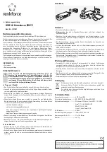
6. Mechanical Information 


Figure 6.1 Mechanical Information Diagram 


E1

E

D

D1

b

e

C1

A2

A

L1

L


 0.

25


GAUGE PLANE

SEATING PLANE

A1

SYMBOLS MIN. 

MAX. 

A -- 

1.60 

A1 0.05 0.15 
A2 1.35 1.45 

b 0.17 

0.27 

c1 0.09 0.16 

D 12.00 

BSC 

D1 10.00 

BSC 

E 12.00 

BSC 

E1 10.00 

BSC 

e 0.50 

BSC 

L 0.45 

0.75 

L1 1.00 

REF 


1.  JEDEC OUTLINE: MS-026 BCD 

2.  DIMENSIONS D1 AND E1 DO NOT 

INCLUDE MOLD PROTRUSION.  

ALLOWABLE PROTRUSION IS 0.25mm 

PER SIDE.   D1 AND E1 ARE MAXIMUM 

PLASTIC BODY SIZE DIMENSIONS 

INCLUDING MOLD MISMATCH. 

3.  DIMENSION b DOES NOT INCLUDE 

DAMBAR PROTRUSION.   ALLOWABLE 

DAMBAR PROTRUSION SHEALL NOT 

CAUSE THE LEAD WIDTH TO EXCEED 

THE MAXIMUM b DIMENSION BY MORE 

THAN 0.08mm. 


AU9525 USB Smart Card Reader Controller V1.00W 

8

Summary of Contents for AU9525

Page 1: ...AU9525 USB Smart Card Reader Controller Technical Reference Manual...

Page 2: ...AU9525 USB Smart Card Reader Controller...

Page 3: ...without prior notice Alcor Micro Corp makes no warranty for the use of its products and bears no responsibility for any error that appear in this document Specifications are subject to change without...

Page 4: ...Memo...

Page 5: ...m 2 3 Pin Assignment 3 4 System Architecture and Reference Design 6 4 1 AU9525 Block Diagram 6 5 Electrical Characteristics 7 5 1 Recommended Operating Conditions 7 5 2 General DC Characteristics 7 5...

Page 6: ...agram 3 Figure 4 1 AU9525 Block Diagram 6 Figure 6 1 Mechanical Information Diagram 8 List of Tables Table 3 1 AU9525 Pin Descriptions 4 Table 5 1 Recommended Operating Conditions 7 Table 5 2 General...

Page 7: ...speed Based on ISO7816 implementation Embedded enhanced 8051 MCU Support Firmware upgrade mechanism ISP In System Programming Support PC Smart Card industry standard PC SC 1 0 Support CT API Support M...

Page 8: ...9525 By connecting the card reader to a ATM or E Commerce etc Figure 2 1 Block Diagram PC w ith U SB H ost Controller U SB Keyboard H ub U SB D ow ns tream Port Application Program s Corporate N etw o...

Page 9: ...28 29 30 31 32 1 2 3 4 5 6 7 8 9 10 11 12 13 14 15 16 AVCC AVSS XTAL1 XTAL2 PSWOUTB PSWOUTA VCC5V BVCC USB_DP USB_DM BVSS ChipRstN LCD_EN GPI_0 LCD_RW GPI_1 LCD_RS SCL SDA LCD_BL LCD_CS1 Key_Row4 Key_...

Page 10: ...rved need pull down 17 LCD_RS O LCD driver dedicated I O line LCD Register Select 18 SCL I O EEPROM Clock need pull high 19 SDA I O EEPROM Data need pull high 20 LCD_BL O LCD Background Light control...

Page 11: ...r dedicated I O lines Data pin5 47 LCD_Dat6 I O LCD driver dedicated I O lines Data pin6 48 LCD_Dat7 I O LCD driver dedicated I O lines Data pin7 49 TXD O RS232 output pin 50 RXD I RS232 input pin 51...

Page 12: ...1 AU9525 Block Diagram XCVR Processor EEPROM Interface ROM Smart Card FIFO Reset 3 3V Voltage Regulator USB Upstream Port Card Eject Card Reset Card Insert Optional 256 Bytes EEPROM Card Data Card Clo...

Page 13: ...high current no pull up or pull down 1 1 A IOZ Tri state leakage current 10 10 A CIN Input capacitance Pad Limit 5 F COUT Output capacitance Pad Limit 5 F CBID Bi directional buffer capacitance Pad Li...

Page 14: ...BSC e 0 50 BSC L 0 45 0 75 L1 1 00 REF 1 JEDEC OUTLINE MS 026 BCD 2 DIMENSIONS D1 AND E1 DO NOT INCLUDE MOLD PROTRUSION ALLOWABLE PROTRUSION IS 0 25mm PER SIDE D1 AND E1 ARE MAXIMUM PLASTIC BODY SIZE...

Page 15: ...tions for the personal computer and consumer electronics markets worldwide We specialize in USB solutions and focus on emerging technology such as USB and IEEE 1394 The company offers a range of semic...

Reviews: