


Albalá Ingenieros | Manual
DVM3001C02
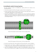
the mounting frame.
7 - Affix the main board to the mounting frame using the two screws included on the
front panel.
After these steps, the module is ready to be connected to other equipment.
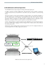
3.7. Interconnection
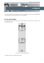
The following figure shows the DVM3001C02 module rear board connector layout.
Rear view of the DVM3001C02
The DVM3001C02 module provides two inputs (IN-A, IN-B), four digital video outputs
(OUT0-A to OUT3-A, OUT0-B to OUT3-B) and two analog composite video outputs
(OUT4-A, OUT5-A, OUT4-B, OUT5-B) for each of its two sections. The connectors labeled
OUT0-A/BYPASS-A or OUT0-B/BYPASS-B corresponds to the outputs whose signals are
protected with bypass relays such that if the power supply fails or the module is
extracted signal continuity from the input is maintained.
14
Summary of Contents for DVM3001C02
Page 2: ...DVM3001C02 ...
Page 4: ...DVM3001C02 ...
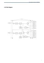
Page 7: ...Albalá Ingenieros Manual DVM3001C02 1 3 Block diagram 7 ...
Page 8: ...Albalá Ingenieros Manual DVM3001C02 DVM3001C02 8 ...
Page 16: ...Albalá Ingenieros Manual DVM3001C02 DVM3001C02 16 ...
Page 24: ...Albalá Ingenieros Manual DVM3001C02 DVM3001C02 24 ...
Page 26: ...Albalá Ingenieros Manual DVM3001C02 DVM3001C02 26 ...


