background image

ATS9462 User Manual 


i


Copyright © 2007 - 2008 AlazarTech. All rights reserved. 


AlazarTech Contact Information 

AlazarTech, Inc. 
3551 St-Charles, Unit 640 
Kirkland, Quebec 
Canada H9H 3C4 
 
Telephone: (514) 633-0001 
Fax: (514) 633-0021 
 
E-mail:  [email protected] 
Web site:  www.alazartech.com  

 
To comment on the documentation for ATS9462, send e-mail to 
[email protected]


Information required when contacting AlazarTech for technical support: 

Owned by: 


___________________________ 

Serial Number:   

___________________________ 

Purchase Date:  

___________________________ 

Purchased From: 

___________________________ 

Software Driver Version:  ___________________________ 

SDK Version:   

___________________________ 

AlazarDSO Version: 

___________________________ 

AlazarDSO Version: 

___________________________ 

Operating System: 

___________________________ 


Summary of Contents for ATS9462

Page 1: ...ATS9462 User Manual 16 Bit 180 MS s Waveform Digitizer for PCI Express Bus Written for Hardware Version 1 1 January 2008 Edition Part Number 9462 USR 1 ...

Page 2: ......

Page 3: ...ATS9462 send e mail to support alazartech com Information required when contacting AlazarTech for technical support Owned by ___________________________ Serial Number ___________________________ Purchase Date ___________________________ Purchased From ___________________________ Software Driver Version ___________________________ SDK Version ___________________________ AlazarDSO Version __________...

Page 4: ...c be liable for any damages arising out of or related to this document or the information contained in it The latest user manual can be found on the AlazarTech Inc web page at www alazartech com support downloads htm EXCEPT AS SPECIFIED HEREIN ALAZARTECH INC MAKES NO WARRANTIES EXPRESS OR IMPLIED AND SPECIFICALLY DISCLAIMS ANY WARRANTY OF MERCHANTABILITY OR FITNESS FOR A PARTICULAR PURPOSE CUSTOME...

Page 5: ... OR ERRORS ON THE PART OF THE USER OR APPLICATIONS DESIGNER ADVERSE FACTORS SUCH AS THESE ARE HEREAFTER COLLECTIVELY TERMED SYSTEM FAILURES ANY APPLICATION WHERE A SYSTEM FAILURE WOULD CREATE A RISK OF HARM TO PROPERTY OR PERSONS INCLUDING THE RISK OF BODILY INJURY AND DEATH SHOULD NOT BE RELIANT SOLELY UPON ONE FORM OF ELECTRONIC SYSTEM DUE TO THE RISK OF SYSTEM FAILURE TO AVOID DAMAGE INJURY OR ...

Page 6: ...liance mark Consult the FCC web site http www fcc gov for more information FCC DOC Warnings This equipment generates and uses radio frequency energy and if not installed and used in strict accordance with the instructions in this manual and the CE Mark Declaration of Conformity may cause interference to radio and television reception Classification requirements are the same for the Federal Communi...

Page 7: ...ocuments htm This web page lists all DoCs by product family Select the appropriate product to download or read the DoC Certain exemptions may apply in the USA see FCC Rules 15 103 Exempted devices and 15 105 c Also available in sections of CFR 47 The CE Mark Declaration of Conformity will contain important supplementary information and instructions for the user or installer Environmental Complianc...

Page 8: ...he ATS9462 Linux Driver 25 Updating ATS9462 Driver 26 CHAPTER 3 HARDWARE OVERVIEW 28 Input Connectors 29 Signal Connections 30 Analog Input 31 Pipelined ADC 32 Multiple Record Acquisition 32 Specifying Record Length 32 Specifying Pretrigger Depth 32 Specifying Record Count 32 Amplifier Bypass Option 33 Calibration 37 Master Slave Operation 38 Restrictions 39 Optional External Clock 41 Fast Externa...

Page 9: ...ATS9462 User Manual 1 Chapter 1 Introduction This chapter describes the ATS9462 and lists additional equipment ...

Page 10: ...dth DIP switch selectable Amplifier Bypass Mode for optimum signal integrity Half length PCI Express 4 lane card Analog trigger channel with software selectable level and slope Software selectable AC DC coupling and 1MΩ 50Ω input impedance Software selectable bandwidth limit switch independent for each channel Pre trigger and Post Trigger Capture with Multiple Record capability NIST traceable cali...

Page 11: ...orms and offer seamless integration with compliant systems If your application requires more than two channels for data acquisition you can synchronize multiple digitizers on all platforms using a Master Slave SyncBoard 460 Detailed specifications of the ATS9462 digitizers are listed in Appendix A Specifications ...

Page 12: ...DK software development kit that comes with sample programs and a reference manual describing the API For programming in LabVIEW you must purchase the ATS VI virtual instrument library that comes with a high level easy to use VI that makes integrating the ATS9462 into your own system very simple With the upcoming release of Linux drivers for ATS9462 it will also be possible to program your ATS9462...

Page 13: ...sktop oscilloscope To launch the Scope Soft Front Panel select Start Programs AlazarTech AlazarDSO The following screen will be displayed If you connect the input to a signal generator and click on Start button you should see the signal on the screen AlazarDSO has been designed to be very intuitive and uses a user interface similar to most of today s digital oscilloscopes ...

Page 14: ...fy Note that only the Asynchronous API functions should be used when programming the ATS9462 Traditional API and AutoDMA API is not supported ATS VI LabVIEW VI ATS VI allows you to integrate the ATS9462 into your own LabVIEW program A high level VI is supplied that requires very few controls to get started Note that only the AsyncDMA vi virtual instrument vi should be used when programming the ATS...

Page 15: ...for ATS9462 can be used for programming the ATS9462 under Linux operating system A binary driver is supplied that has been compiled for Fedora Core 5 Kernel 2 6 running on an i386 platform Sample program is supplied in C The API is identical to the Windows API ...

Page 16: ...des and accessories for use with your ATS9462 digitizer ATS9462 External Clock Upgrade ATS9462 Master Slave SyncBoard 2 position ATS9462 Master Slave SyncBoard 4 position ATS9462 Master Slave SyncBoard 8 position AlazarDSO Stream To Disk Module AlazarDSO Plug In Development Kit ...

Page 17: ...ATS9462 User Manual 9 Chapter 2 Installation and Configuration This chapter describes how to unpack install and configure your ATS9462 ...

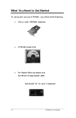
Page 18: ...u Need to Get Started To set up and use your ATS9462 you will need the following One or more ATS9462 digitizers ATS9462 Install Disk For Master Slave operation only SyncBoard of appropriate width SyncBoard 2X for up to 2 digitizers ...

Page 19: ...ATS9462 User Manual 11 SyncBoard 4X for up to 4 digitizers SyncBoard 8X for up to 8 digitizers ...

Page 20: ...recautions Ground yourself via a grounding strap or by holding a grounded object Touch the antistatic package to a metal part of your computer chassis before removing the digitizer from the package Remove the digitizer from the package and inspect the digitizer for loose components or any other sign of damage Notify AlazarTech if the digitizer appears damaged in any way Do not install a damaged di...

Page 21: ...river when prompted by the operating system 3 Install AlazarDSO software that allows you to setup the hardware acquire signals and view and archive them 4 Optionally install the ATS SDK software development kit or ATS VI LabVIEW VI or ATS Linux Linux drivers which enable you to programmatically control the ATS9462 The following paragraphs will guide you through this process in a step by step manne...

Page 22: ...room as possible between your ATS9462 and other hardware Always screw the digitizer bracket to the chassis in order to create a stable and robust connection to chassis ground In the absence of such a connection ATS9462 is not guaranteed to operate within the specifications listed elsewhere in this manual Some motherboards may have a 16 lane connector but only one of the lanes is connected to the m...

Page 23: ...s that will be configured as a Master Slave system make sure that you insert all cards in adjacent slots The connector on the SyncBoard that is labeled as M Master must be inserted into the Master Slave connector of the left most digitizer if you are facing the BNC connectors of the ATS9462 digitizers ...

Page 24: ...imum number of digitizers supported by your SyncBoard the unused SyncBoard connectors must be on the right hand side of the digitizers if you are facing the BNC connectors of the ATS9462 digitizers Once you have completed this step you should power the computer on ...

Page 25: ...e not covered here Installation of Multiple ATS9462 Digitizers If you are installing multiple ATS9462 digitizers the operating system will detect one card at a time and you will have to go through the driver installation setup as many times as you have cards If you are installing multiple ATS9462 digitizers under Windows 98SE you will be prompted to reboot the computer after each installation You ...

Page 26: ...ll display the Welcome to the Found New Hardware Wizard Click Next b Operating system will display the Install Hardware Device Driver dialog box Select the radio button next to the text Display a list of the known drivers for this device so that I can choose a specific driver Click Next c Operating system will display the Hardware Type dialog box Select System devices d Operating system will displ...

Page 27: ...ke sure the AlazarTech ATS9462 PCI Digitizer is selected Then click Next h Operating system will display the Update Driver Warning This warning is meant to tell you that Windows does not recognize the hardware Click Yes i Operating system will display the Start Device Driver Installation dialog box Click Next System will copy all necessary files to the appropriate folders j Operating system will d...

Page 28: ...ver a Operating System will display the Welcome to the Found New Hardware Wizard Click on the radio button next to the text Install from a list or specific location Advanced Click Next b Operating System will display the Please choose your search and installation options dialog box Click on the radio button next to the text Don t search I will choose the driver to install Click Next c Operating sy...

Page 29: ... you want to install for this hardware dialog box again Make sure the AlazarTech ATS9462 PCI Digitizer is selected highlighted Click Next g Operating system will display the Update Driver Warning This warning is meant to tell you that Windows does not recognize the hardware Click Yes h System will copy all necessary files to the appropriate folders i Operating system will display the Completing th...

Page 30: ...the AlazarDSO folder on the ATS9462 Install Disk Run Setup exe program Follow the instructions on the screen If you are installing AlazarDSO after having downloaded the installation file from AlazarTech web site Download AlazarDSO installation file from www alazartech com support downloads htm Unzip the file downloaded in the previous step Browse to the folder that contains the unzipped file Setup...

Page 31: ...TS9462 Insert the ATS SDK or ATS VI CD Software installation will start automatically If for any reason installation does not start automatically run the SETUP EXE program Follow the instructions on the screen Note that you must have already installed the ATS9462 drivers for any of the sample programs included with the ATS SDK or ATS VI to work properly ...

Page 32: ...ully responsible for compiling drivers for their own Linux operating system To install Linux drivers in a Fedora Core 5 system follow the instructions listed below 1 Copy the supplied RPM file to the target machine 2 Double click on the RPM icon This will install the driver as well as associated applications 3 Reboot the PC Note that if you do not reboot the PC the driver will not be loaded The RP...

Page 33: ...ATS9462 User Manual 25 Compiling the ATS9462 Linux Driver These instructions will be provided in a future version of the ATS9462 User Manual ...

Page 34: ...anel by opening Start Settings Control Panel b Open System Properties dialog box by selecting or double clicking on the System menu c Click on Hardware tab in the dialog box d Click on Device Manager button 2 Device Manager lists all hardware devices in your computer AlazarTech PCI digitizers are listed within System Devices 3 Expand the System Devices list 4 Double click on the AlazarTech ATS9462...

Page 35: ...ATS9462 User Manual 27 9 To complete the installation follow the instructions provided in the section labeled a Installing ATS9462 Driver in Windows 2000 Or b Installing ATS9462 Driver in Windows XP ...

Page 36: ...TS9462 and describes the signal connections Following is a high level block diagram of ATS9462 P C I B U S CH A Analog Front End CH B Analog Front End EXT Trig Analog Front End A D C A D C FPGA FPGA contains FIFO that allows data streaming FPGA also contains the entire PCI Express Bus Interface Trigger Comparators EXT Clock Input Protection PCI Bus Interface ASIC ...

Page 37: ...nections one standard BNC female connector for the TRIG IN External Trigger input and one standard BNC female connector for AUX I O Auxiliary Input or Output The following pictorial shows the various connectors available on the digitizer bracket Identification LED For future use Auxiliary I O Default is TRIG OUT External Trigger TRIG IN Channel B Channel A Optional External Clock ...

Page 38: ...e the ECLK input for clocking the ATS9462 in applications that require an external clock Consult the chapter Optional External Clock for details on various types of clocking schemes available AUX I O connector can be used for outputting TRIG OUT signal a 5 V TTL signal synchronous with the on board trigger signal and the sampling clock Note that the Trigger Output connector can also be configured ...

Page 39: ...grammable input range of 5 V or 1 V The CH A CH B and EXT inputs have a software programmable coupling selection between AC and DC Use AC coupling when your AC signal contains a large DC component Without AC coupling it is difficult to view details of the AC component with a large DC offset and a small AC component such as switching noise on a DC supply If you enable AC coupling you remove the lar...

Page 40: ... board memory This allows you to capture rapidly occurring triggers in OCT ultrasound or radar applications Note that pre trigger data cannot be acquired using ATS9462 Specifying Record Length Record Length is specified in number of sample points It must be a minimum of 128 points and can be specified with a 16 sample resolution Specifying Pretrigger Depth ATS9462 cannot acquire pre trigger data S...

Page 41: ...mic performance ATS9462 allows the user to set and reset the Amplifier Bypass Option using on board DIP switches The user can bypass the amplifier on any one or both channels of ATS9462 The following picture of the secondary side of ATS9462 board shows the location of four DIP switches used for this purpose 2 DIP switches per channel ...

Page 42: ...s always ON connected Thus the input signal travels through the input amplifier and attenuator circuitry before being digitized by the ADC IC To select Amplifier Bypass Mode the switch settings must be changed such that Switch 1 is always ON connected and Switch 2 is always OFF disconnected This would bypass all input amplifier circuitry and inject the signal directly into the driving amplifier of...

Page 43: ...er Manual 35 The default setting of all four of the DIP switches is shown below ON 1 2 The black square represents the plastic tab for the switch Note that the actual tab may not be black It may in fact be white ...

Page 44: ... shown below To re insert the input amplifier in the signal path i e to remove Amplifier Bypass Option change the DIP Switch setting of the Near and Far switches for that particular channel to be the same as the factory set default NOTE THAT ANY SETTINGS OTHER THAN THE ONES SHOWN ABOVE ARE ILLEGAL AND MAY CAUSE DAMAGE TO THE ATS9462 ANALOG CIRCUITRY ON 1 2 ON 1 2 ...

Page 45: ...e is listed on the CALIBRATION sticker affixed to your ATS9462 digitizer Externally recalibrate the ATS9462 when this calibration interval has expired This requires three very simple steps 1 Verify whether or not ATS9462 is still within its specifications If it is then your calibration can be extended by another one year period 2 If not perform calibration i e make adjustments to the circuit until...

Page 46: ...er products on the market ATS9462 does not suffer from clock jitter between master and slave digitizers The unique design of the ATS9462 clock circuit provides a buffered copy of the Master digitizer s clock to itself and all the slave digitizers thereby maintaining a very low skew between Master and Slave digitizer clocks Note that an ATS9462 Master Slave system is capable of triggering from any ...

Page 47: ...lave system Good Installation Bad Installation You must connect the appropriate SyncBoard to all of the ATS9462 digitizers in your system Note that all SyncBoards are polarized so you cannot make a mistake in inserting them If you are using fewer than the maximum number of digitizers allowed by the SyncBoard make sure that the connector labeled M Master on the SyncBoard is connected to one of the ...

Page 48: ...sample programs supplied with ATS SDK or ATS VI or any custom software written using ATS SDK or ATS VI If you run AlazarDSO or your own software that loads the ATSApi DLL after having installed a SyncBoard the ATS9462 driver will automatically recognize that the digitizers are now configured as Master Slave As such there is no need to have your hardware upgraded or modified in any way to go from a...

Page 49: ...reduction in data conversion quality Aside from phase noise the clock signal for a pipelined ADC must also have a duty cycle close to 50 This maximizes the dynamic performance of the ADC See Fast External Clock section below for more details External clock input impedance is fixed at 50 Ohms External clock input coupling can be set to AC or DC under software control There are three types of Extern...

Page 50: ...Clock This setting must be used when the external clock frequency is slower than the lower limit of Fast External Clock In this range the input clock is tracked by the 125 MHz internal clock and a sample is taken on every rising or falling clock edge As such there will be a timing error of 0 to 8 nanoseconds For low bandwidth signals this error can be considered to be negligible Note that if you u...

Page 51: ...inux operating systems The Effects of the Operating System Windows and Linux are not real time operating systems i e the operating system cannot guarantee a deterministic response time to an event such as an interrupt or a software generated event This means that if software has to play any appreciable part in data transfer then the data throughput cannot be guaranteed as the operating system will...

Page 52: ...gitizer board if they are all guaranteed to be 100 compatible and interoperable with each other with deterministic interrupt latencies and if you will get your money back if the system does not work at your PRF rates with your software Here is an excerpt from a FAQ section of one such supplier of RTOS Question How do system configuration and CPU selection impact the interrupt latency Answer Hardwa...

Page 53: ...nt and maintenance and limit the number of suppliers for other hardware components Dual Port Memory The basic throughput problem faced by digitizers is that almost all of them use single port memory i e if you are reading data from the acquisition memory you cannot capture into it and vice versa This requires a software handshake which is heavily dependent on the operating system response time ATS...

Page 54: ...ne and fully asynchronous driver that uses overlapped IO these tasks can be paralleled In other words when software is re arming DMA channel 0 DMA channel 1 is already transferring data to host memory At the fastest transfer rates users must use large buffers say 8 Megabytes to ensure that the DMA channel 1 does not finish before the DMA channel 0 is re armed and vice versa Note that if data throu...

Page 55: ... bus as soon as the ATS9462 is armed for acquisition It is important to note that triggering is disabled in this mode Continuous AutoDMA buffers do not include headers so it is not possible to get trigger time stamps A BUFFER_OVERFLOW flag is asserted if the Data FIFO overflows The amount of data to be captured is controlled by counting the number of buffers acquired Acquisition is stopped by an A...

Page 56: ... to PC host memory at sustained rates up to 720 MB s without causing an overflow This is the recommended mode for RF signal recording that has to be started at a specific time e g based on a GPS pulse Stream To Disk Any one of the AutoDMA modes can be combined with a fast disk drive to create a very efficient and low cost data streaming system AlazarDSO Stream To Disk module sold separately allows...

Page 57: ...e PCI Express revision 1 0a or higher Transceiver speed 2 5 Gbps Number of lanes 4 Compatibility mechanical x4 x8 and x16 slots Compatibility electrical x1 x4 x8 and x16 slots Power Requirements 12V 1 5 A typical for ATS9462 3 3V 1 0 A typical for ATS9462 Physical Size Single slot half length PCI card 4 2 inches x 7 5 inches Weight 750 g I O Connectors ECLK SMA female connector CH A CH B TRIG IN A...

Page 58: ... s single shot Fast External Clock Full Scale Input ranges 1 MΩ 200mV 400mV 800mV 2V 4V 8V and 16V software selectable 50 Ω 200mV 400mV 800mV 2V and 4V software selectable DC accuracy 2 of full scale in all input ranges Input coupling AC or DC software selectable Input impedance 50Ω or 1MΩ 1 in parallel with 30 pF 10pF software selectable Input protection 1MΩ 28V DC peak AC for CH A CH B and EXT o...

Page 59: ...0 MS s 5 MS s 2 MS s 1 MS s 500 KS s 200 KS s 100KS s 50 KS s 20KS s 10KS s 5 KS s 2 KS s 1 KS s Internal Clock accuracy 25 ppm Dynamic Parameters Typical values measured using a randomly selected ATS9462 with Amplifier Bypass Mode Input was provided by a HP8656A signal generator followed by a 9 pole 1 MHz band pass filter TTE Q36T 1M 100K 50 720B Input frequency was set at 1 MHz and output amplit...

Page 60: ...S s 160 MS s 161 MS s 162 MS s 163 MS s 164 MS s 165 MS s 166 MS s 167 MS s 168 MS s 169 MS s 170 MS s 171 MS s 172 MS s 173 MS s 174 MS s 175 MS s 176 MS s 177 MS s 178 MS s 179 MS s 180 MS s Note that the accuracy and stability of these sampling frequencies is dependent on the accuracy and stability of the 10 MHz Clock Referece input supplied by the user Triggering System Mode Edge triggering wi...

Page 61: ... full scale input Input protection 28V DC peak AC without external attenuation Coupling AC or DC software selectable Auxiliary I O AUX I O Signal Direction Input or Output software selectable Output by default Output Types Trigger Output Busy Output Software controlled Digital Output Input Types Trigger Enable Software readable Digital Input Output Amplitude 5 Volt TTL Synchronization Synchronized...

Page 62: ...54 ATS9462 User Manual ...

Page 63: ......

Page 64: ...ALAZAR TECHNOLOGIES INC 3551 St Charles Unit 640 Kirkland QC CANADA H9H 3C4 Tel 514 633 0001 Fax 514 633 0021 E mail info alazartech com Web www alazartech com www pci digitizers com ...

Reviews: