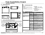
IV.
Mechanical Drawing
All dimensions are in centimeters
39.1
2.95
0
25.2
4.60
0
34.4
11.0
4.92 TYP
38.1
30.6
7.62
KEY LOCK
28.0
0
5.38
0
0
0
0
0
V.
Power Limited Wiring Requirements
VI.
Troubleshooting Guide
Fault Output
v
Form "C" Relay Contacts rated 1 Amp @
24VDC.
v
Relay Contacts labeled in the non-operational
(fault) condition.
v
Fail-safe; active until an actual fault condition.
Visual Indicators
1. AC Presence LED1: Green LED
2. System OK LED3: Green LED
3. LED2 (Red LED) serves no user function.
Fault Conditions
Green LED extinguishes on:
Low AC / No AC / Blown AC Fuse
Low Battery / Output
Blown Battery Fuse
VII
Troubleshooting Chart
Rewire battery set.
Incorrect battery
hook-up.
Remove primary power and batteries, then
replace fuse. CAUTION.
Blown battery fuse.
4) No battery back-up
Verify switch settings in Section III.
Incorrect switch
setting.
Measure xfmr secondary voltage. If not within
proper range, replace transformer.
Incorrect or defective
xfmr.
Rewire battery set.
Incorrect battery
hook-up.
Remove system load and batteries; check
system output voltage. If OK recheck system
requirements, and/or measure output current
draw with an ammeter.
The system load is
greater than the
supply capability.
Check battery condition and replace if needed.
Defective battery.
3) Incorrect output voltage
Check xfmr secondary voltage at PC board
"Low Voltage AC Connection". If voltage is not
present, replace xfmr.
Loss of transformer
(xfmr) power.
Remove primary power and batteries, then
replace fuse. CAUTION.
Blown AC fuse.
Check AC primary supply.
Loss of AC power.
2) Green "AC" LED is not
illuminated.
See Symptom 4.
Blown battery fuse.
See Symptom 3.
Low battery.
"Fault" Relay Contacts transfer.
See Symptom 2.
Low AC / No AC /
Blown AC fuse.
1) Green "System OK" LED
extinguishes.
Correction Procedure
Possible Cause
Symptoms
Power Supply/Battery Chargers
Installation Instructions
AlarmSaf
w
65A Industrial Way
w
Wilmington, MA 01887-3499
w
(978) 658-6717
w
FAX: (978) 658-8638 Web Site: www.alarmsaf.com
52-008B
032497
AC FUSE (AGC-10)
BATT FUSE (AGC-10)
Power-limited and nonpower-limited circuit wiring must remain separated by at least 1cm within the cabinet.
All power-limited circuit wiring and nonpower-limited wiring must enter and exit the cabinet through different
knockouts. An example is shown below, although different knockouts may be used. The use of conduit is
optional for power-limited wiring.
AC Primary Power
Wiring
(Nonpower-limited)
Run through either
knockout at the top
left corner.
Output Circuit
Wiring
(Power-limited)
Run through either
knockout on the
right side.
Battery Storage Space - 12.2cmH x 38cmW x 10cmD
For further assistance, please contact the AlarmSaf Technical Service Department.


