Use these instructions in conjunction with the complete installation
manual for this product.
Your Alarm.com Dealer Portal:
www.alarm.com/dealer
The Mobile Tech App:
https://alarmadmin.alarm.com/mobile
Sign in using the dealer credentials provided by Alarm.com.
Create a customer account
a. From the Alarm.com Dealer website or MobileTech app, select
Customers >
Create New Customer
.
b. Add the customer’s address and contact information.
c. Enter the 10-digit serial number, located on the barcode sticker of the panel.
Install the panel
a. Inspect the panel and peripheral devices before installation to ensure they are
not damaged.
b. Install the iotega on a flat, stable surface, free from vibration and shock, and
near a power outlet.
c. Connect the panel to the Customer’s router with a CAT-5/6 Ethernet cable.
d. Pull out the battery tape.
e. Connect the barrel jack of the plug-in adapter to the power connector on the
back of the panel. Route the power cable through the strain relief channel on the
bottom of the panel then plug the adapter into an AC outlet.
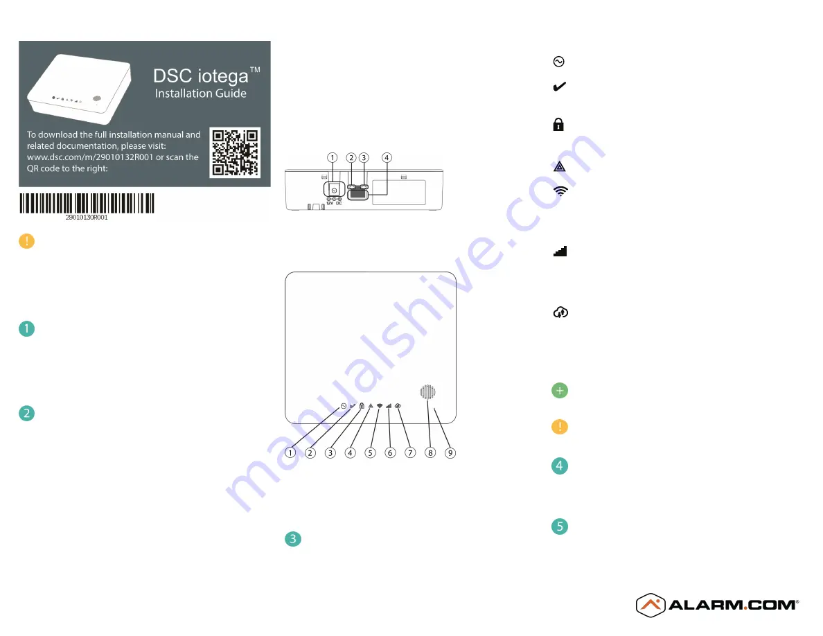
The iotega powers up once plugged in. The power-up sequence is as follows:
l
The integrated keypad numbers illuminate in sequence.
l
The Power LED illuminates after approximately 40 seconds.
l
The Ethernet Link Speed LED illuminates steady green and the
Ethernet Link Activity LED flashes rapidly to indicate that a
connection is being made.
l
The Remote Connection LED illuminates steady green to indicate a
connection to the Alarm.com server has been made over Cell or
Ethernet.
1. Power Connector
2. Ethernet Link Speed LED
3. Ethernet Link Activity LED
4. Ethernet Port
1. Power LED
6. Cellular Signal Strength LED
2. Ready to Arm LED
7. Remote Connection LED
3. Armed LED
8. Siren
4. Trouble LED
9. Microphone
5. WiFi Signal Strength LED
Verify panel communications
Review the LED indicators on the iotega panel.
LED operational status is shown below.
Power
On steady (green) when AC power is connected.
Ready to Arm
On steady (green) when partition is in a ready to arm mode. No fire or CO
alarms are present.
Armed
On steady (red) when partition is armed.
Off when partition is disarmed or audible alarm annunciation is off.
Trouble
On steady (amber) when system troubles are present.
Wi-Fi® Signal Strength
On steady (green) when strong signal connection .
On steady (amber) when weak signal connection.
On steady (red) when no signal, Off when no Wi-Fi detected.
Cellular Signal Strength
On steady (green) when strong signal connection .
On steady (amber) when weak signal connection.
On steady (red) when no signal or no connection detected.
Remote Connection Status
On steady (green) when Link to remote server is active.
On flashing (red) when link to remote server is active but has failed to
communicate.
Off when link to remote server is not active.
For more information on LED indicators, see “Controls and
Indicators” in the iotega installation manual.
When replacing the battery, use a battery pack suitable for the
application. Refer to “Specifications” in the iotega installation
manual.
Confirm signaling with the Alarm.com backend
On MobileTech or the Dealer Portal, navigate to
Remote Toolkit
and run the
communication test. This test confirms the unit is communicating with
Alarm.com.
Enroll sensors (zones) and peripheral devices
Navigate to
Equipment > Sensors > Add a Sensor
to put the panel into Add
Mode. Select Auto-Learn or Remote Add.


