


Copyright © 2012 Alarm.com
|
www.alarm.com
|
v3.0
3
Concord 4 CDMA Module
|
Installation Guide
Figure 6: Case tamper switch installation
Power Up
To power up the module and panel and start communication between
them, do the following:
1)
Verify that all wiring between the panel and module is correct.
2)
Connect the backup battery and restore AC power to the panel.
Note:
Whenever the module is added or changed, you must remove panel
power and reapply it for the panel and module to communicate successfully.
3)
Enter installer program mode and turn off the “Access Code Lock”
feature (Security menu). This
MUST
be set to off for the system to
communicate
with Alarm.com. The module PWR LED should turn on.
After a few seconds, the module BUS and AUTO LEDs should flash to
indicate successful communication with the panel.
4)
Verify that CDMA status LED L1 is not flashing any errors (see
Module
Status LEDs
on page 4). Also, verify that LED L4 is flashing a CDMA
signal level of two or higher. Otherwise, relocate the module. If LED
L1 and LED L4 are not flashing, and LED L2 and LED L3 are flashing
together, the module is in PowerSave mode and the battery needs to
be charged.
5)
Perform an installer CDMA manual phone test.
At a system touchpad,
•
Enter “
8
” + [
installer code]
+ “
3”
•
Disarm the panel by entering “
1
” +
[installer code]
within 10
seconds of starting the phone test. Before doing the manual
phone test, the bottom red status LED should be on and the
yellow status LED should be flashing. The yellow LED will stay on
solid once the manual phone test is completed.
Note:
Do not press any system touchpad buttons during the five to eight
minutes or the time will not set. During this time, the keypad will go in and
out of programming mode and will beep several times.
emPower Z-Wave Device Installation
The Concord 4 CDMA module features integrated support for
Alarm.com’s emPower
TM
solution with built-in Z-Wave capabilities. Z-
Wave devices can be enrolled into the system using a push button on
the top of the module. LED L2 and L5 are used to indicate Z-Wave
statuses and errors. See the
Module Status LEDs
section on page 4 and
the Z-Wave LED status and error patterns in
Table 6
on page 4 for more
information.
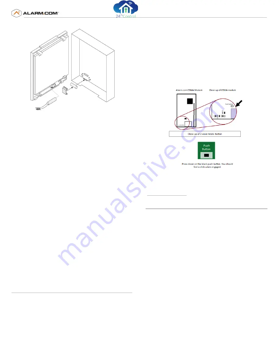
To enroll a Z-Wave device, enter Z-Wave add mode by pressing and
holding the push button on the module until LED L2 begins flashing in a
4-blink pattern. (See
Figure 7
for the location of the push button.) Once
in add mode, trigger the Z-Wave device to enroll it. (Refer to the device-
specific instructions for information on tripping device.)
To remove a Z-Wave device, you must first enter add mode using the
instructions above. Once LED L2 begins flashing in a 4-blink pattern,
release the push button. To enter delete mode, press and hold the push
button again until LED L2 begins flashing in a 2-blink pattern. Trigger the
Z-Wave device to remove it.
Figure 7: Location of Z-Wave Push Button on Concord CDMA Module
For additional information on enrolling and troubleshooting Z-Wave
devices, refer to the full emPower installation instructions and
documentation available on the Alarm.com Dealer Site
(
www.alarm.com/dealer
).
Gateway Status LEDs
The status LEDs, located on the left side of the module (
Figure 1
on page
1), indicate the current signal and status of the Wireless Gateway
Module. The bottom red LED indicates if the module is in range and if it
is registered. The yellow and green LEDs indicate the message status.
The top LED is not used.
Red LED
On:
The module is in range and registered with the network.
Off:
The module is out of range and not registered with the network.
Blinks:
The module is registered with the network, but out of range.
Yellow LED
On:
LED on after the first message has been sent by the module and
received by Alarm.com.
Off:
LED off until a message has been sent by the module.
Blinks:
The first message is being sent by the module.
Green LED
Off:
The LED is off as soon as Alarm.com receives a message from the
module (off most of the time).
Blinks:
A message is being sent by the module.
N
Module Back Plate
Module Cover
Magnet
Magnet Clip
Reed switch
2.0 KΩ


