3.1.3 Connecting Receivers
Refer to fig. 4 or 5.
3.2 Assigning IP Addresses
Refer to fig. 6.
Important!
Important!
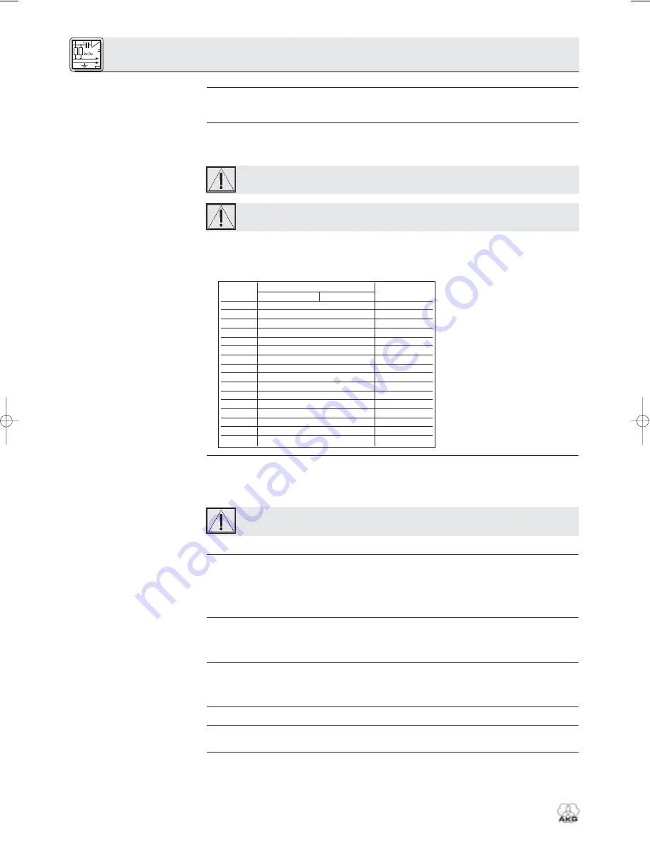
Refer to Table 1.
Table 1: IP addresses for 16 hubs.
3.2.1 Setting IP addresses
Refer to Table 1.
Important!
3.3 Connecting to Power
Refer to fig. 4.
3.4 Powering Up/Down
3.5 Setting Up the Computer
3.6 Testing the Hubs
3.7 Operating the Network
8
HUB 4000
3. Plug the other end of each network cable to an unused output on (one of) your Ethernet hub(s).
1. Be sure
not to use any cables other than the supplied data cables
with RJ 11 connectors.
2. Connect the DATA socket on each SR 4000 receiver to one of the RECEIVER DATA sockets SR 1 to
SR 8 on the HUB 4000 rear panel.
•
Each unit within the network needs its own, unambiguous IP address.
•
The IP address of each HUB 4000 is factory-set to 192.168.0.4. The related combination of the ADR
DIP switches is "1111".
Before connecting the unit to power, check that the IP address (ADR combination) of the
unit is not identical to any other IP address previously assigned within the network. IP
addresses assigned to multiple units may cause data transmission problems.
If you daisy-chain several HUB 4000s, remember to assign to the hubs consecutive IP
addresses in ascending order to make sure the computer will correctly identify and con-
trol all HUB 4000s.
•
You may assign any IP address between 192.168.0.4 and 192.168.0.19 to the HUB 4000 directly con-
nected to the computer (hub no. 1). Assign the next higher IP address to the next HUB 4000 in your
chain referring to Table 1. Enter the selected IP address of the first HUB 4000 in the MCS 4000 con-
trol program to enable the program to control the hubs correctly.
1. Remove the cover of the ADR switch bank.
2. Check that the current IP address has not been assigned to any other unit within the network yet.
3. If the current IP address has been assigned to another unit within the network, set a new IP address
that has not been assigned to any other unit.
Upon having set a new IP address, switch power to the unit off and back on. The new IP
address will not become active before you have switched power back on.
4. Replace the ADR switch bank cover.
1.
Check that the AC mains voltage stated on the included power supply is identical to the AC
mains voltage available where you will use your system. Using the power supply with a differ-
ent AC voltage may cause damage to the unit.
2. Plug the DC cable on the included power supply into the 12 V/500 mA socket on the HUB 4000 rear
panel and screw down the DC connector.
3. Plug the power cable on the power supply into a convenient power outlet.
1. To switch power to the unit on, press the ON/OFF key.
The status LED next to the ON/OFF key will be lit, the blue DATA TRANSFER LEDs will illuminate start-
ing from the center and extinguish to indicate the unit is initialized and ready to operate.
2. To switch power to the unit off, press the ON/OFF key again.
Make sure to assign an unambiguous IP address to the network card on the computer to which you con-
nected the HUB 4000(s). Select a network card address that differs from any HUB 4000 IP address in the
network but is within the same network segment, preferably 192.168.0.1. The subnet mask of the hub
network segment is always 255.255.255.0.
To test the hubs, use the
ping <ip address>
command, e.g.,
ping 192.168.0.4
.
To control the entire network (hubs and connected receivers) from your computer, you will need the
optional MCS 4000 software. Refer to the MCS 4000 manual.
3 Setting Up
Hub no.
ADR switch positions
IP address
0 .. down
1 … up
1
1111
192.168.0.4
2
1110
192.168.0.5
3
1101
192.168.0.6
4
1100
192.168.0.7
5
1011
192.168.0.8
6
1010
192.168.0.9
7
1001
192.168.0.10
8
1000
192.168.0.11
9
0111
192.168.0.12
10
0110
192.168.0.13
11
0101
192.168.0.14
12
0100
192.168.0.15
13
0011
192.168.0.16
14
0010
192.168.0.17
15
0001
192.168.0.18
16
0000
192.168.0.19
3199_03_HUB4000_fsch 11.11.2003 9:06 Uhr Seite 8
Summary of Contents for HUB 4000
Page 26: ...26 HUB 4000 Notizen Notes Notes Note Notas Notas ...
Page 27: ...27 HUB 4000 Notizen Notes Notes Note Notas Notas ...
Page 29: ...A B C Fig 3 1 A C B D D Fig 3 2 ...
Page 31: ......


