


78
Chapter 10—Using FX
Z4/Z8 User Guide—Version 1.0
10 Using FX
About the FX
This chapter explains how to configure the Z8’s four FX processors (optional on the Z4).
Programs and Multis can be routed to the FX via the FX Send buses A–D. See “Config-
uring Keygroup Programs” on page 51 and “Applying FX to Parts” on page 72 for more
information. FX processors can be linked for use with stereo Samples, or connected in
series. FX settings are stored in Multis.
Configuring FX Inputs
The input source for each FX processor can be set as follows.
1
Press the FX button.
The FX button indicator lights up and the PATCH page appears.
2
In the “Input” column, select the Input parameter for the FX processor
whose inputs you want to configure, and use the JOG dial to select one of
the following options.
SEND A–D:
Selects FX Send A, B, C, or D as the input source. The same FX Send can
be selected for one or more FX processors.
FX 1–4:
Selects the output of FX processor 1–4 as the input source, allowing you to con-
nect FX in series. Since the input to each FX processor is mono, and the output is stereo,
the output of the preceding FX processor is mixed into mono before being fed to the sub-
sequent FX processor, as shown below.
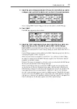
In the following example, FX1 and FX2 apply distortion and reverb in series to the signal
routed from Send A. The output of FX1 is set to “OFF.” The input source for FX2 is set
to “FX1.” Samples routed to Send A are processed by FX1 (distortion), whose output is
fed to the input of FX2 (reverb), the output of which is fed to L-R.
Note: While Sample recording is in progress, FX4 does not feed its output signal to any
of the outputs. However, if it’s used in series, its output signal is fed to the subsequent
FX processor.
FX1
FX2
FX3
FX4
Input
Output
FX1
FX2
FX3
FX4
Input
Output
Summary of Contents for Z4
Page 106: ......


