


Connections
English - 20
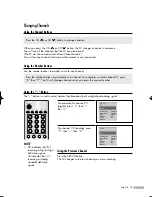
Cable with a Cable Box that Descrambles Some (But Not All) Channels
To complete this connection you will need a two-way splitter, an RF (A/B) switch, and four coaxial
cables (which you can buy from your AKAI dealer or any electronics store).
1
Find and disconnect the
cable that is connected to
the ANTENNA IN terminal
of your Splitter.
This terminal might be
labeled “ANT IN”, “VHF IN”
or simply, “IN”. Connect this
cable to a two-way splitter.
2
Connect a coaxial cable
between an OUT terminal
of the splitter and the IN
terminal of the Cable box.
3
Connect a coaxial cable
between the ANTENNA OUT
terminal of the Cable box
and the B-IN terminal of the
RF (A/B) switch.
4
Connect another cable
between the other OUT
terminal on the splitter and
the A–IN terminal on the
RF (A/B) switch.
5
Connect the last coaxial
cable between the OUT
terminal of the RF (A/B)
switch and the ANT 1 IN
(CABLE) on the TV.
After you’ve made this connection, set the A/B switch to the “A” position for normal viewing.
Set the A/B switch to the “B” position to view scrambled channels. (When you set the A/B switch
to “B”, you will need to tune your Set-Top Box to the Cable box's output channel, which is usually
channel 3 or 4.)
BP68-00548A-00Eng(018~029) 9/12/05 9:37 AM Page 20
Summary of Contents for PT50DL14
Page 1: ...Owner s Instructions PT50DL14...
Page 2: ......
Page 8: ...AKAI...
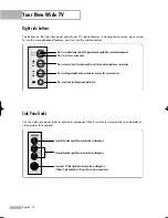
Page 9: ...Your New Wide TV...
Page 17: ...Connections...
Page 28: ...AKAI...
Page 29: ...Operation...
Page 37: ...English 37 Remote Control Codes VCR Codes DVD Codes Cable Box Codes...
Page 44: ...AKAI...
Page 45: ...Channel Control...
Page 51: ...Picture Control...
Page 71: ...Sound Control...
Page 80: ...AKAI...
Page 81: ...Special Features...
Page 104: ...AKAI...
Page 105: ...Appendix...
Page 111: ......
Page 112: ...BP68 00548A 00...


