AJAX 7296 User Manual Download Page 14

Plus receiver processes the signal and opens (by default, the output can be also
set for closing) the wire output corresponding to the sensor.

The alarm system’s central unit reads the output opening as the sensor’s zone
opening and sends an alarm signal. If it is mentioned that the central unit zone
must have high resistance between the receiver’s output and the central unit
zone, the resistor with nominal required by the central unit must be placed with
serial connection.

Observe the polarity while connecting the wires!

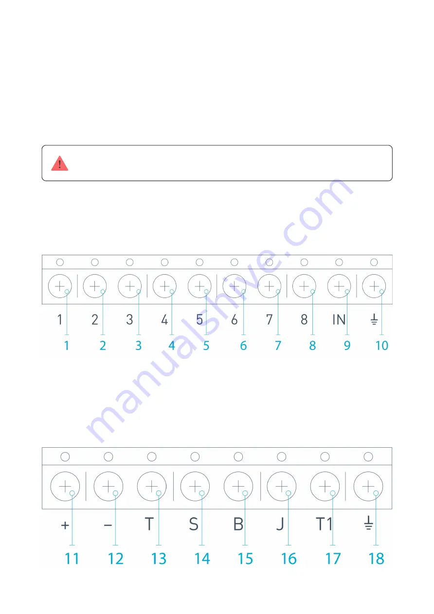
3. The outputs with numbers 1–8 (Picture 17) correspond to 8 main nominal
alarm zones.

Picture 17. Main outputs and input “IN” of the receiver

Other 5 outputs of ocBridge Plus are service zones and correspond to the
service inputs of the alarm system central unit.

Picture 18. ocBridge Plus receiver’s service outputs and power supply

Summary of Contents for 7296

Page 1: ...e When the system is in passive mode wireless sensors switch to power saving mode which makes it possible to extend signi cantly battery life If the receiver ocBridge Plus is connected to the wire cen...

Page 2: ...ones 4 mini USB connector 5 red and green light indicators consult the table for the description 6 opening tamper button 7 green power supply indicator 8 battery for backup saving 9 IN digital input 1...

Page 3: ...correct one over it ocBridge Plus will not work with the PC s con gurator program If the wrong driver was installed at rst it is necessary to uninstall it through Windows programs uninstall then rebo...

Page 4: ...con guration is downloaded system is armed system is disarmed No green and red light The receiver is in in the operating mode the system is disarmed Permanent red light The receiver is in operating m...

Page 5: ...n it below QR code then click the Search button Picture 4 When the search indicator bar begins to move it is necessary to turn on the sensor The registration request is sent only when the sensor is be...

Page 6: ...rties activate the checkbox Additional input Picture 5 If a sensor for example a LeaksProtect is designed for working 24 h activate in the checkbox properties 24 h active 24 h sensors and normal senso...

Page 7: ...two concrete walls is approximately 30 m 98 4 ft Take into consideration if you move the sensor even 10 cm 4 in it is possible to improve signi cantly the quality radio signal between the sensor and t...

Page 8: ...indication bar Blinks twice per second Low signal No bar Short ashes each 1 5 seconds No signal Please install the sensors in the places with the signal level of 3 or 2 bars Otherwise the sensor may...

Page 9: ...us settings in le on PC Save con gurations to le upload to ocBridge Plus the settings con guration saved on the computer Open the existing con guration start the rmware upgrade Firmware update clear a...

Page 10: ...or saving data in ocBridge memory and for reading current con guration settings Sensors handling 6 Events memory page stores information about alarming events Picture 12 service events Picture 13 and...

Page 11: ...stics table Picture 14 it is easy to handle important data from each sensor sensor s location in speci c zone and in general in the network to observe the battery state in each sensor to track the tam...

Page 12: ...for the detector to send its rst status and will transmit the current system settings in response to it light green lighting during 1 second is turning on when the status is received from the sensor...

Page 13: ...the alarm system central unit panel Do not install the receiver in the metal box it will worsen considerably the radio signal receiving from the wireless sensors If installation in the metal box is in...

Page 14: ...between the receiver s output and the central unit zone the resistor with nominal required by the central unit must be placed with serial connection Observe the polarity while connecting the wires 3 T...

Page 15: ...t 9 Input IN Wire input for connecting to the central unit output for alarm system arming disarming 10 Ground for connection to the central unit 11 Power supply plus 12 Power supply minus 13 T Tamper...

Page 16: ...ation zones and arm disarm zones Picture 19 Zone type is selected when the zone is created consult Sensors handling Picture 19 Selecting zone type The alarm zone can be set Picture 20 as NC normally c...

Page 17: ...d light 3 is on Picture 1 Automation zone can be set as NC or NO Picture 21 When the Impulse way to react is chosen the zones reacts to all activations with opening closing depending on Initial state...

Page 18: ...le set of sensors connected to the receiver are set to passive mode except for the sensors ticked as 24 h active with the initial state restore the sensors are set to active and the red light is on In...

Page 19: ...espond to service zones Picture 18 Service zones are used for sending operation data to the central unit Service outputs functioning is adjustable Picture 23 they can be impulse of bistable ones It is...

Page 20: ...riod multiplied by the parameter Passes number Picture 25 By default if ocBridge Plus does not receive 40 heartbeats from sensor successfully it generates an Lost connection alarm Picture 25 Service o...

Page 21: ...Connection you should select a COM port where ocBridge Plus is connected Then it is necessary to select Firmware upgrade in drop down menu and then pressing the button Select le to show the le path t...

Page 22: ...f new receiver it is necessary to switch off the power switch on all the sensors alternately to wait for some seconds for the capacitor of the sensors to discharge and then to turn the sensors on agai...

Page 23: ...ble Alerts and events logs Available External antenna connection Available Firmware update Available Tamper protection Available opening detaching Number of wireless inputs outputs 13 8 4 1 1 Power su...

Page 24: ...ars after the purchase and does not apply to the pre installed battery If the device does not work correctly you should rst contact the support service in half of the cases technical issues can be sol...

Reviews: