


– 32 –
DESCRIPTION
REF. NO.
KANRI
NO.
PART NO.
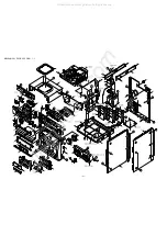
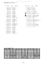
MECHANICAL PART LIST 1 / 1
DESCRIPTION
REF. NO.
KANRI
NO.
PART NO.
COLOR NAME TABLE
Basic color symbol
Color
Basic color symbol
Color
Basic color symbol
Color
B
Black
C
Cream
D
Orange
G
Green
H
Gray
L
Blue
LT
Transparent Blue
N
Gold
P
Pink
R
Red
S
Silver
ST
Titan Silver
T
Brown
V
Violet
W
White
WT
Transparent White
Y
Yellow
YT
Transparent Yellow
LM
Metallic Blue
LL
Light Blue
GT
Transparent Green
LD
Dark Blue
DT
Transparent Orange
GM
Metallic Green
YM
Metallic Yellow
DM
Metallic Orange
!
!
1 8A-MA3-095-010 RING,VOL
2 8A-MA3-090-010 KNOB,RTRY MAIN
3 87-NF8-220-010 DMPR,150
4 8A-MA5-208-010 SPR-T,EJECT 2
5 87-NF4-217-110 HLDR,LOCK 2
6 86-NF9-224-010 SPR-C,LOCK
7 82-NF5-229-010 PLATE,LOCK
8 8A-MA3-026-110 BOX,CASS R
9 8A-MA3-056-010 WINDOW,CASS R
10 8A-MA5-036-010 PANEL,CASS R 5
11 8A-MA3-025-110 BOX,CASS L
12 8A-MA3-055-010 WINDOW,CASS L
13 8A-MA5-035-010 PANEL,CASS L 5
14 8A-MA5-041-010 PANEL,FUN 4F
15 81-532-080-010 LABEL, CASS. COMPT
16 8A-MA5-102-010 REFLECTOR,FUN 4F
17 8A-MA5-051-010 WINDOW,DISP RDS 5
18 8A-MA5-207-010 SPR-T,EJECT 1
19 8A-MA5-034-010 PANEL,CD
20 8A-MA5-037-010 PANEL ASSY,TRAY 5
21 87-NF4-216-010 HLDR,LOCK 1
22 87-B00-002-010 BADGE,AIWA 30 ABS SIL
23 8A-MA3-093-010 KNOB ASSY,RTRY JOG
24 8A-MA5-031-010 PANEL,FR RDS 5
25 8A-MA5-080-010 KEY ASSY,GEQ 5M
26 8A-MA3-084-010 KEY ASSY,FF
27 8A-MA5-066-010 KEY,FUN 4F
28 8A-MA5-081-010 KEY ASSY,PLAY
29 8A-MA3-071-010 KEY,TIMER
30 8A-MA3-073-010 KEY,ENTER
31 8A-MA3-210-010 GUIDE,LED OPE
32 8A-MA3-057-010 WINDOW,TOP
33 8A-MA3-020-110 CABI,TOP
34 8A-MA3-075-010 KEY,POWER
35 8A-MA3-101-010 REFLECTOR,POWER
36 87-MA5-203-010 GUIDE,FL
37 8A-MA3-061-010 KEY,CD
38 8A-MA5-001-210 CABI,FR U 5
39 88-MA1-208-210 JOINT,CABI
40 8A-DB8-209-010 HLDR,PWB PT
41 84-ZG1-245-210 CAP,OPTICAL
42 8A-MA5-013-010 CABI,REAR KSTNM
43 8A-MA5-046-010 PANEL,SIDE R 5
44 87-099-811-010 PLUG,ADPTR CONV(K)<K>
45 87-064-185-010 HLDR,WIRE
46 87-A80-148-010 AC CORD ASSY,E BLK<EZ>
46 87-A80-143-010 AC CORD ASSY,E BLK<K>
47 87-085-185-010 BUSHING, AC CORD (E)
48 87-MA3-062-010 FOOT, H17
49 8A-MA5-045-010 PANEL,SIDE L 5
50 8A-MA3-070-010 KEY RDS
A 87-067-703-010 TAPPING SCREW, BVT2+3-10
B 87-591-095-410 TAPPING SCREW, QIT+3-8 (GLD)
C 87-NF4-224-010 S-SCREW,IT3B+3-8 CU
D 87-067-581-010 BVT2+3-15 W/O
E 87-067-688-010 BVTT+3-6
F 87-067-975-010 S-SCREW,1T+4-8
G 87-067-641-010 UTT2+3-8(W/O SLOT)BL
H 87-067-758-010 BVT2+3-12 W/O SLOT
I 87-067-579-010 TAPPING SCREW, BVT2+3-8
J 87-078-060-010 3-10
!
All manuals and user guides at all-guides.com
Summary of Contents for Z-L500
Page 12: ...SCHEMATIC DIAGRAM 1 MAIN 1 2 AMP SECTION 12 All manuals and user guides at all guides com ...
Page 13: ...SCHEMATIC DIAGRAM 2 MAIN 2 2 TUNER SECTION 13 All manuals and user guides at all guides com ...
Page 15: ...SCHEMATIC DIAGRAM 3 MICON DECK 15 All manuals and user guides at all guides com ...
Page 17: ...SCHEMATIC DIAGRAM 4 CNTL KEY CD 17 All manuals and user guides at all guides com ...
Page 19: ...SCHEMATIC DIAGRAM 5 PT 19 All manuals and user guides at all guides com ...
Page 23: ... 23 IC BLOCK DIAGRAM IC BU2099FV IC LC72131D All manuals and user guides at all guides com ...
Page 24: ... 24 IC M61506FP IC LA1843 All manuals and user guides at all guides com ...
Page 25: ... 25 IC M61503FP IC BU1920FS All manuals and user guides at all guides com ...
Page 27: ... 27 ANODECONNECTION All manuals and user guides at all guides com ...