


– 29 –
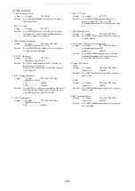
< TUNER SECTION >
1. Clock Frequency Check
Settings : • Test point :
TP2 (CLK)
Method :
Set to MW 1602kHz and check that the test point is
2052kHz
±
45Hz.
2. MW VT Check
Settings : • Test point :
TP1 (VT)
Method :
Set to MW 1602kHz and check that the test point is
less than 8.0V. Then set to MW 531kHz and check
that the test point is more than 0.6V.
3. MW Tracking Adjustment
Settings : • Test point :
TP5 (Lch), TP6 (Rch)
• Adjustment location : L951 (1/3)
Method :
Set to MW 999kHz and adjust L951 (1/3) so that the
test point becomes maximum.
4. LW VT Adjustment
Settings : • Test point :
TP1 (VT)
• Adjustment location : L942
Method :
Set to LW 144kHz and adjust L942 so that the test
point becomes 1.3V
±
0.05V.
Then set to LW 290kHz and check that the test point
is less than 8.0V.
5. LW Tracking Adjustment
Settings : • Test point :
TP5 (Lch), TP6 (Rch)
• Adjustment location :
L941 ........................... 144kHz
TC943 ......................... 290kHz
Method :
Set up TC943 to center before adjustment. The level at
144kHz is adjusted to MAX by L941. Then the level
at 290kHz is adjusted to MAX by TC943.
6. AM IF Adjustment
Settings : • Test point :
TP5 (Lch), TP6 (Rch)
• Adjustment location :
L802 ........................... 450kHz
7. FM VT Check
Settings : • Test point :
TP1 (VT)
Method :
Set to FM 108.0MHz and check that the test
point is less than 8.0V. Then set to FM
87.5MHz and check that the test point is more than
0.5V.
8. FM Tracking Check
Settings : • Test point :
TP5 (Lch), TP6 (Rch)
Method :
Set to FM 98.0MHz and check that the test point is
less than 13dB
µ
V.
9. DC Balance / Mono Distortion Adjustment
Settings : • Test point :
TP3, TP4 (DC balance)
• Adjustment location : L801
• Input level :
60dB
µ
V
Method :
Set to FM 98.0MHz and adjust L801 so that the
distortion is minimum. Then check the voltage
between TP3 and TP4 is 0V
±
300mV.
10. Output Level Check
<MW>
Settings : • Test point :
TP5 (Lch), TP6 (Rch)
• Input level :
74dB
µ
V
Method :
Set to MW 999kHz and check that the test point is
50mV
±
3dB.
<FM>
Settings : • Test point :
TP5 (Lch), TP6 (Rch)
• Input level :
60dB
µ
V
Method :
Set to FM 98.0MHz and check that the test point is
100mV
±
3dB.
11. FM Separation Check
Settings : • Test point :
TP5 (Lch), TP6 (Rch)
• Input level :
60dB
µ
V
Method :
Set to FM 98.0MHz and check that the test point is
more than 12dB.
All manuals and user guides at all-guides.com
Summary of Contents for Z-L500
Page 12: ...SCHEMATIC DIAGRAM 1 MAIN 1 2 AMP SECTION 12 All manuals and user guides at all guides com ...
Page 13: ...SCHEMATIC DIAGRAM 2 MAIN 2 2 TUNER SECTION 13 All manuals and user guides at all guides com ...
Page 15: ...SCHEMATIC DIAGRAM 3 MICON DECK 15 All manuals and user guides at all guides com ...
Page 17: ...SCHEMATIC DIAGRAM 4 CNTL KEY CD 17 All manuals and user guides at all guides com ...
Page 19: ...SCHEMATIC DIAGRAM 5 PT 19 All manuals and user guides at all guides com ...
Page 23: ... 23 IC BLOCK DIAGRAM IC BU2099FV IC LC72131D All manuals and user guides at all guides com ...
Page 24: ... 24 IC M61506FP IC LA1843 All manuals and user guides at all guides com ...
Page 25: ... 25 IC M61503FP IC BU1920FS All manuals and user guides at all guides com ...
Page 27: ... 27 ANODECONNECTION All manuals and user guides at all guides com ...