– 15 –
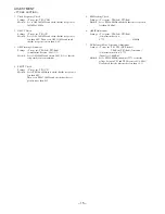
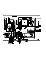
< TUNER SECTION >
1. Clock Frequency Check
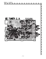
Settings : • Test point : TP2 (CLK)
Method : Set to AM 1602kHz and check that the test point is
2052kHz
±
45Hz.
2. AM VT Check
Settings : • Test point : TP1(VT)
Method : Set to AM 1602kHz and check that the test point is
less than 8.0V. Then set to AM 531kHz and check
that the test point is more than 0.6V.
3. AM Tracking Adjustment
Settings : • Test point : TP6(Lch), TP7(Rch)
• Adjustment location : L981(1/3)
Method : Set to AM 999kHz and adjust L981 (1/3) so that the
test point becomes maximum.
4. FM VT Check
Settings : • Test point : TP1 (VT)
Method : Set to FM 108.0MHz and check that the test point is
less than 8.0V.
Then set to FM 87.5MHz and check that the test
point is more than 0.5V.
5. FM Tracking Check
Settings : • Test point : TP6(Lch), TP7(Rch)
Method : Set to FM 98.0MHz and check that the test point is
less than 9.0dB
µ
V.
6. AM IF Adjustment
Settings : • Test point : TP6(Lch), TP7(Rch)
• Adjustment location :
L772 ................................................ 450kHz
7. DC Balance / Mono Distortion Adjustment
Settings : • Test point : TP3, TP4 (DC Balance)
TP6(Lch), TP7(Rch) (Distortion)
• Adjustment location : L771
• Input level : 60dB
µ
V
Method : Set to FM 98.0MHz and adjust L771 so that the
voltage between TP3 and TP4 becomes 0V
±
0.04V.
Next, check that the distortion is less than 1.3%
ADJUSTMENT
Summary of Contents for XR-M800 HC
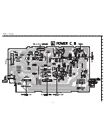
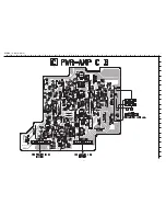
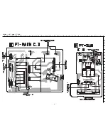
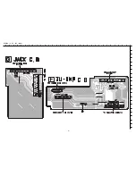
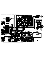
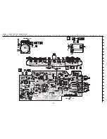
Page 10: ... 10 SCHEMATIC DIAGRAM 1 POWER PWR AMP PT MAIN PT SUB TU INF JACK ...
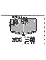
Page 12: ... 12 SCHEMATIC DIAGRAM 2 FRONT LED 1 3 ...
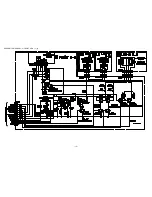
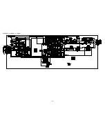
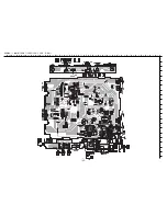
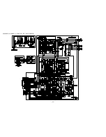
Page 14: ... 14 SCHEMATIC DIAGRAM 3 TUNER ...
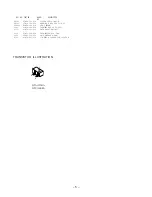
Page 21: ... 21 TRANSISTOR ILLUSTRATION DTA144TKA B C E E C B 2SA19790 Y ...
Page 23: ... 23 SCHEMATIC DIAGRAM 1 MAIN FRONT LED3 LED L LED R RM DECK HEAD DRIVE FRAME ...
Page 25: ... 25 SCHEMATIC DIAGRAM 2 FUNC KEY CD DOOR MOTOR ...
Page 28: ... 28 SCHEMATIC DIAGRAM 3 CD MICON 1 2 ...


