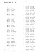
Aiwa XR-EM70 Service Manual Download Page 6

– 6 –

DESCRIPTION

REF. NO.

KANRI

NO.

PART NO.

DESCRIPTION

REF. NO.

KANRI

NO.

PART NO.

 C391     87-010-787-080    C-CAP,U 0.022-25 KB

 C403     87-010-759-080    C-CAP,U, 0.1-25F

 C409     87-012-282-080    CAP, U 4700P-50

 C422     87-016-459-080    CAP,E 470-10 M SMG

 C426     87-A12-088-080    CAP,E 2.2-50 SMG

 C427     87-A12-088-080    CAP,E 2.2-50 SMG

 C439     87-A10-304-080    CAP,M 0.056-50 J

 C440     87-A10-304-080    CAP,M 0.056-50 J

 C441     87-A10-307-080    CAP,M 0.1-50 J

 C442     87-A10-307-080    CAP,M 0.1-50 J

 C443     87-010-785-080    C-CAP,U0.015-25BK

 C444     87-010-785-080    C-CAP,U0.015-25BK

 C451     87-012-275-080    C-CAP,U 1200P-50 KB

 C452     87-012-275-080    C-CAP,U 1200P-50 KB

 C460     87-A12-087-080    CAP,E 1-50 SMG

 C461     87-A12-087-080    CAP,E 1-50 SMG

 C462     87-A12-087-080    CAP,E 1-50 SMG

 C463     87-A12-087-080    CAP,E 1-50 SMG

 C464     87-A12-065-080    CAP,E 33-10 SMG

 C465     87-012-271-080    C-CAP,U 560P-50 KB

 C466     87-012-271-080    C-CAP,U 560P-50 KB

 C467     87-012-274-080    C-CAP,U 1000P-50 KB

 C468     87-012-274-080    C-CAP,U 1000P-50 KB

 C470     87-012-274-080    C-CAP,U 1000P-50 KB

 C471     87-012-274-080    C-CAP,U 1000P-50 KB

 C472     87-A12-471-080    C-CAP,U 1000P-50 J SL

 C473     87-010-759-080    C-CAP,U, 0.1-25F

 C474     87-012-278-080    C-CAP,U 2200P-50 KB

 C475     87-012-278-080    C-CAP,U 2200P-50 KB

 C481     87-A12-090-080    CAP,E 4.7-50 SMG

 C482     87-A12-090-080    CAP,E 4.7-50 SMG

 C483     87-A12-088-080    CAP,E 2.2-50 SMG

 C484     87-A12-088-080    CAP,E 2.2-50 SMG

 C485     87-012-282-080    CAP, U 4700P-50

 C486     87-012-282-080    CAP, U 4700P-50

 C487     87-010-785-080    C-CAP,U0.015-25BK

 C488     87-010-785-080    C-CAP,U0.015-25BK

 C489     87-010-785-080    C-CAP,U0.015-25BK

 C490     87-010-785-080    C-CAP,U0.015-25BK

 C495     87-A12-087-080    CAP,E 1-50 SMG

 C496     87-A12-087-080    CAP,E 1-50 SMG

 C497     87-A12-087-080    CAP,E 1-50 SMG

 C498     87-A12-087-080    CAP,E 1-50 SMG

 C503     87-010-759-080    C-CAP,U, 0.1-25F

 C504     87-010-759-080    C-CAP,U, 0.1-25F

 C505     87-010-759-080    C-CAP,U, 0.1-25F

 C506     87-010-759-080    C-CAP,U, 0.1-25F

 C509     87-010-759-080    C-CAP,U, 0.1-25F

 C510     87-010-759-080    C-CAP,U, 0.1-25F

 C511     87-010-759-080    C-CAP,U, 0.1-25F

 C512     87-010-759-080    C-CAP,U, 0.1-25F

 C519     87-A10-520-000    CAP,E 3300-35 M SMG

 C520     87-A10-520-000    CAP,E 3300-35 M SMG

 C521     87-010-928-000    CAP,E 4700-25 M SMG

 C522     87-A10-011-090    CAP,E 2200-25 SMG

 C525     87-A10-918-080    CAP,E 100-16 SMG

 C526     87-A10-918-080    CAP,E 100-16 SMG

 C530     87-A12-079-080    CAP,E 100-35 SMG

 C531     87-A12-062-080    CAP,E 100-10 SMG

 C532     87-012-286-080    CAP, U 0.01-25

 C534     87-A12-072-080    CAP,E 100-25 SMG

 C535     87-010-367-040    CAP,E 4.7-25 M BP SRA

 C536     87-A12-067-080    CAP,E 330-16 SMG

 C538     87-012-282-080    CAP, U 4700P-50

 C539     87-012-278-080    C-CAP,U 2200P-50 B

 C540     87-A12-062-080    CAP,E 100-10 SMG

 C541     87-A12-079-080    CAP,E 100-35 SMG

 C545     87-010-831-080    C-CAP,U,0.1-16F

 C546     87-A12-064-080    CAP,E 1000-10 SMG

 C547     87-010-831-080    C-CAP,U,0.1-16F

 C560     87-A12-089-080    CAP,E 3.3-50 SMG

 C561     87-A12-071-080    CAP,E 47-25 SMG

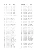
 C861     87-010-405-080    CAP, ELECT 10-50V<EZ>

 C862     87-010-759-080    C-CAP,U, 0.1-25F<EZ>

 C863     87-012-199-080    CAP  220P<EZ>

 C864     87-012-199-080    CAP  220P<EZ>

 C865     87-012-274-080    CHIP CAP,U 1000P-50B<EZ>

 C866     87-012-270-080    CAP, U 470P-50<EZ>

 C867     87-012-286-080    CAP, U 0.01-25<EZ>

 C868     87-010-405-080    CAP, ELECT 10-50V<EZ>

 C869     87-012-286-080    CAP, U 0.01-25<EZ>

 C870     87-012-184-080    C-CAP,U 33P-50 CH<EZ>

 C871     87-012-180-080    C-CAP,U 22P-50 CH<EZ>

 C872     87-012-280-080    CAP, U 3300P-50<EZ>

 C873     87-012-280-080    CAP, U 3300P-50<EZ>

 CN230    84-722-638-010    CONN,5P H WHT EH

 CN301    87-A60-625-010    CONN,8P V 2MM JMT

 CN402    87-A60-189-010    CONN,16P V TUC-P16P-B1

 CN403    87-099-195-010    CONN,7P V BLK 6216

 CN410    87-099-719-010    CONN,30P TYK-B(X)

 CN502    87-A90-510-010    HLDR,WIRE 2.5-9P

 CNA201   8B-CJZ-640-010    CONN ASSY,9P TID-A(200)

 FB405    87-A90-896-080    F-BEAD, 035600STY7

 FB406    87-A90-896-080    F-BEAD, 035600STY7

 J404     87-A61-711-010    JACK,PIN 2P MSP-242V-01 PBSN

 JW432    87-A90-896-080    F-BEAD, 035600STY7

 JW433    87-A90-896-080    F-BEAD, 035600STY7

 L301     87-A50-049-010    COIL,TRAP 85K(COI)

 L302     87-A50-049-010    COIL,TRAP 85K(COI)

 L351     87-007-342-010    COIL,OSC 85K BIAS

 L402     87-A50-610-010    COIL,1UH K(MDEC)

 L403     87-A50-610-010    COIL,1UH K(MDEC)

 L861     87-005-847-080    COIL,2.2UH(CECS)<EZ>

 L871     87-A50-027-010    COIL,1 POLE MPX(TOK)

 L872     87-A50-027-010    COIL,1 POLE MPX(TOK)

 R129     87-A00-258-080    RES,M/F 0.22-1W J

 R130     87-A00-258-080    RES,M/F 0.22-1W J

 R131     87-A00-258-080    RES,M/F 0.22-1W J

 R132     87-A00-258-080    RES,M/F 0.22-1W J

 SFR351   87-024-436-080    SFR,47K RH063EC

 SFR352   87-024-436-080    SFR,47K RH063EC

 TH101    87-A91-042-080    C-THMS,100K 55001

 TH102    87-A91-042-080    C-THMS,100K 55001

 TM401    87-A61-712-010    TERMINAL, 4P SP MSP-324V1-01

 X862     87-A70-307-010    VIB,XTAL 4.332MHZ CSA-309ST<EZ>
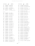
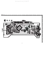
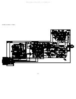
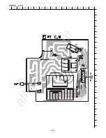
FRONT C.B

 C50      87-012-274-080    CHIP CAP,U 1000P-50B

 C51      87-A12-091-040    CAP,E 10-50 SMG

 C52      87-A12-310-080    C-CAP,U 0.01-50 K B

 C53      87-A12-310-080    C-CAP,U 0.01-50 K B

 C54      87-A12-310-080    C-CAP,U 0.01-50 K B

 C55      87-A12-310-080    C-CAP,U 0.01-50 K B

 C56      87-A12-310-080    C-CAP,U 0.01-50 K B

 C57      87-A12-310-080    C-CAP,U 0.01-50 K B

 C60      87-A10-025-080    C-CAP,U 0.22-16 ZF

 CN50     87-099-040-010    CONN,23P H BLK 6216

 CN53     87-099-212-010    CONN,05P V BLK 6216

 CNA52    8B-CLX-617-010    CONN ASSY,9P DECK PL-CONT

 D50      87-A41-062-040    LED,LTL-1CHEE-012A RED

 D51      87-A41-062-040    LED,LTL-1CHEE-012A RED

 D52      87-A41-062-040    LED,LTL-1CHEE-012A RED

 D53      87-A41-062-040    LED,LTL-1CHEE-012A RED

 D54      87-A41-062-040    LED,LTL-1CHEE-012A RED

 FC050    88-923-091-110    FF-CABLE,23P 1.25 90MM

 FC053    88-905-231-110    FF-CABLE,5P 1.25 230MM

 S50      87-A91-024-180    SW-TACT KSHG611BT

 S51      87-A91-024-180    SW-TACT KSHG611BT

 S52      87-A91-024-180    SW-TACT KSHG611BT

All manuals and user guides at all-guides.com

all-guides.com

Summary of Contents for XR-EM70

Page 1: ...EZ S M Code No 09 019 449 6R1 This Service Manual is the Revision Publishing and replaces Simple Manual of XR EM70 K 71 EZ S M Code No 09 018 449 6T1 REVISION XR EM70 SPEAKER SYSTEM CX LEM70 RC BAT15...

Page 2: ...22 WIRING 7 DECK FRAME DRIVE HEAD 23 IC BLOCK DIAGRAM 24 25 FL HNA 11MS25 GRID ASSIGNMENT AND ANODE CONNECTION 26 IC DESCRIPTION 27 32 ADJUSTMENT TUNER DECK CD FL 33 39 CD TEST MODE 40 MECHANICAL EXPL...

Page 3: ...ONES 32 ohms or more DIGITAL OUT OPTICAL jack CASSETTE DECK Track format 4 tracks 2 channels stereo Frequency response 50 Hz 15000 Hz Recording system AC bias Heads Recording playback X 1 erase X 1 CD...

Page 4: ...rstr lning som verskrider gr nsen f r laserklass 1 PROTECTION OF EYES FROM LASER BEAM DURING SERVICING CAUTION Use of controls or adjustments or performance of proce dures other than those specified h...

Page 5: ...0 CAP E 22 50 SMG C113 87 012 195 080 C CAP U 100P 50CH C114 87 012 195 080 C CAP U 100P 50CH C117 87 A12 317 080 C CAP U 0 1 50 ZF C118 87 A12 317 080 C CAP U 0 1 50 ZF C119 87 012 286 080 CAP U 0 01...

Page 6: ...6F C546 87 A12 064 080 CAP E 1000 10 SMG C547 87 010 831 080 C CAP U 0 1 16F C560 87 A12 089 080 CAP E 3 3 50 SMG C561 87 A12 071 080 CAP E 47 25 SMG C861 87 010 405 080 CAP ELECT 10 50V EZ C862 87 01...

Page 7: ...50CH C603 87 012 195 080 C CAP U 100P 50CH C604 87 012 195 080 C CAP U 100P 50CH C605 87 012 195 080 C CAP U 100P 50CH C606 87 012 195 080 C CAP U 100P 50CH C611 87 010 831 080 C CAP U 0 1 16F C612 8...

Page 8: ...0 C CAP U 18P 50 CH C918 87 012 172 080 CAPACITOR CHIP U 10P CH C919 87 012 184 080 C CAP U 33P 50 CH C920 87 012 184 080 C CAP U 33P 50 CH C921 87 012 180 080 C CAP U 22P 50 CH C922 87 012 174 080 CA...

Page 9: ...TION REF NO KANRI NO PART NO DESCRIPTION REF NO KANRI NO PART NO 8 8 A Resistor Code Chip Resistor Part Coding Figure Value of resistor Chip resistor Wattage Type Tolerance 1 16W 1 10W 1 8W 1608 2125...

Page 10: ...2SC2240 GR BL 2SD655E 2SA1235F 2SA1514K S 2SC2620B 2SC3052F 2SC3906KR 2SC5345SF S O CSD1306E 2SK2158 B C E 2SB1677 2SD2619 2SK360E C B S G D G D S E 2SB1370E B C E G D S 2SK3053 DTA144EKA DTC144EKA KR...

Page 11: ...IN PHONE OPTICAL 32 31 30 29 28 27 26 25 24 23 22 21 20 19 18 17 16 15 14 13 12 11 10 9 8 7 6 5 4 3 2 1 A B C D E F G H I J K L M N O P Q R S T U All manuals and user guides at all guides com a l l g...

Page 12: ...12 SCHEMATIC DIAGRAM 1 MAIN 1 2 PHONE OPTICAL HEAD All manuals and user guides at all guides com...

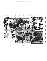
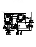
Page 13: ...13 SCHEMATIC DIAGRAM 2 MAIN 2 2 AMP SECTION All manuals and user guides at all guides com...

Page 14: ...14 WIRING 2 FRONT 32 31 30 29 28 27 26 25 24 23 22 21 20 19 18 17 16 15 14 13 12 11 10 9 8 7 6 5 4 3 2 1 A B C D E F G H I J K L M N O P Q R S T U All manuals and user guides at all guides com...

Page 15: ...15 WIRING 3 FL 32 31 30 29 28 27 26 25 24 23 22 21 20 19 18 17 16 15 14 13 12 11 10 9 8 7 6 5 4 3 2 1 A B C D E F G H I J K L M N O P Q R S T U All manuals and user guides at all guides com...

Page 16: ...16 SCHEMATIC DIAGRAM 3 FRONT FL DECK FRAME DRIVE All manuals and user guides at all guides com a l l g u i d e s c o m...

Page 17: ...WIRING 4 CD CD DRIVE CD LOAD 32 31 30 29 28 27 26 25 24 23 22 21 20 19 18 17 16 15 14 13 12 11 10 9 8 7 6 5 4 3 2 1 A B C D E F G H I J K L M N O P Q R S T U All manuals and user guides at all guides...

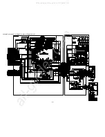
Page 18: ...18 SCHEMATIC DIAGRAM 4 CD CD DRIVE CD LOAD All manuals and user guides at all guides com...

Page 19: ...19 WIRING 5 TUNER 32 31 30 29 28 27 26 25 24 23 22 21 20 19 18 17 16 15 14 13 12 11 10 9 8 7 6 5 4 3 2 1 A B C D E F G H I J K L M N O P Q R S T U All manuals and user guides at all guides com...

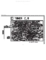
Page 20: ...20 SCHEMATIC DIAGRAM 5 TUNER All manuals and user guides at all guides com...

Page 21: ...21 WIRING 6 PT 15 14 13 12 11 10 9 8 7 6 5 4 3 2 1 A B C D E F G H I J K L M N O P Q R S T U All manuals and user guides at all guides com a l l g u i d e s c o m...

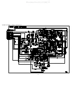
Page 22: ...22 SCHEMATIC DIAGRAM 6 PT All manuals and user guides at all guides com...

Page 23: ...23 WIRING 7 DECK FRAME DRIVE HEAD 15 14 13 12 11 10 9 8 7 6 5 4 3 2 1 A B C D E F G H I J K L M N O P Q R S T U All manuals and user guides at all guides com...

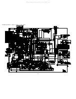
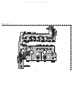
Page 24: ...24 IC BLOCK DIAGRAM All manuals and user guides at all guides com...

Page 25: ...25 All manuals and user guides at all guides com...

Page 26: ...26 FL HNA 11MS25 GRID ASSIGNMENT ANODE CONNECTION GRID ASSIGNMENT ANODE CONNECTION All manuals and user guides at all guides com a l l g u i d e s c o m...

Page 27: ...es the gain 19 JP O Track jump control tri state output 20 JP 21 PCK O Monitors the clock signal for EFM data playback 4 3218MHz when the phase is locked Not used 22 FSEQ O Sync signal detection outpu...

Page 28: ...n not used Connected to 0V 52 FSX O 7 35kHz sync signal output obtained by dividing the oscillator frequency Not used 53 WRQ O Subcode Q standby output 54 RWC I Read write control input Schmitt trigge...

Page 29: ...18 FA O Composes the focusing phase compensation constant between the FD and FA pins 19 FA I Composes the focusing phase compensation constant between the FA and FE pins 20 FE O FE signal output 21 F...

Page 30: ...3MHz is input from the DSP 51 CL I Microprocessor command clock input 52 DAT I Microprocessor command data input 53 CE I Microprocessor chip enable input 54 DRF O DRF detect RF is an output to detect...

Page 31: ...A B tab of cassette detect input 22 I ENC3 VOL I Volume rotary encoder A D input 23 I ENC2 TREBLE I Treble rotary encoder A D input 24 I ENC1 BASS I Bass rotary encoder A D input 25 I KEY2 I Key inpu...

Page 32: ...5 O TUCONT O Tuner ON OFF control output 86 O CLK FUNC O Function IC control clock output 87 O DATA FUNC O Function IC control data output 88 O AMP CONT O Amplifier ON OFF control output Not used 89 V...

Page 33: ...ment Measuring Device Frequency Counter Test Point CLOCK GND 1 Change to MW and adjust the reception frequency of the set to 1602 kHz 2 Check that the test point CLOCK frequency is 2052 kHz 45 Hz 4 VT...

Page 34: ...ile looking at the waveform on the oscilloscope reduce the output level all the way 3 Adjust L951 until the value of the millivoltmeter reaches the maximum 7 Tracking Adjustment LW Requirement Measuri...

Page 35: ...nd reduce the output level all the way 2 Adjust L901 L902 L904 L905 until the value of millivoltmeter reaches the maximum 3 Adjust the S S G setting to 98 0 MHz 75 kHz variation and 66 dBuV for the ou...

Page 36: ...Audio Signal Generator Attenuator Wow Flutter Meter Frequency Counter Oscilloscope Millivolmeter Dummy Load 6 ohm 1 Connect the set to the measuring device as shown in the following diagram 2 Output 1...

Page 37: ...t bond lock 1600B the screws 3 Checking Playback Frequency Reponse Requirements Test Tape TTA 300 315 Hz 10 kHz Test Point Lch Rch GND 1 Insert the test tape TTA 300 and playback 315 Hz and 10 kHz 2 U...

Page 38: ...the 2nd track of TCD 782 3 Check that the RF waveform has the maximum amplitude and the center of the wedge waveform has the clear blank 3 Jitter Check 1 While an oscilloscope is kept connected in the...

Page 39: ...f ATD 001 Check that the noise does not occur and sound skipping does not occur 6 Laser Current Check Do not perform this measurement unless the laser is suspected to be defective 1 Connect a digital...

Page 40: ...is checked If TOC cannot be read focus DRF check search is continued 4 Traverse Mode PAUSE button Normal Tracking servo OFF ON Tracking balance check STOP button to cancel 5 Sled Mode FF button CD TES...

Page 41: ...A A F A C B A A B E E A F A E H D D A D D A CHAS MAIN PWB PWB PWB HT SINK SUB B HT SINK ASSY MAIN 2 HT SINK SUB A PWB PWB PWB PWB 1 2 3 4 5 6 7 8 9 29 11 12 13 14 15 16 17 18 19 20 21 22 23 24 25 26 2...

Page 42: ...8B CLX 012 010 KEY FUNC 9 8B CLX 018 010 REFLECTOR FUNC 10 8B CLX 004 110 PANEL SIDE L 11 8B CLX 203 010 HLDR FL 12 88 923 091 110 FF CABLE 23P 1 25 90MM 13 8B CLX 015 010 KEY EJECT CD 14 8B CLX 016...

Page 43: ...43 TAPE MECHANISM EXPLODED VIEW 1 2 3 4 5 C 1 C 2 7 8 10 11 12 16 13 14 15 D PWB B E 19 17 6ZM 4 A A 18 9 E 6 All manuals and user guides at all guides com...

Page 44: ...ASE 10 8A ZM1 220 010 SPR E CLAMP 11 8A ZM1 216 310 PLATE ASSY CLAMP 12 8A ZM1 234 110 TRAY CASSETTE BL 13 87 045 305 010 MOTOR RF 500TB DC 5V 2MA 14 86 ZL1 210 010 PULLEY MOT 15 8Z ZG4 614 010 F CABL...

Page 45: ...LDR MOT L CUSH G B B 21 A J 22 23 24 25 16 17 19 18 26 a a 47 48 PLATE SHLD DECK 44 43 45 42 41 40 39 38 37 35 34 33 32 36 31 30 29 27 28 46 54 13 3 2 1 4 5 6 53 7 8 8 10 9 11 12 9 15 14 b b I R7NM 52...

Page 46: ...0 GEAR IDLER 32 82 ZM3 616 010 RING MAGNET 4 33 86 ZM1 219 010 CLR REEL SLIP 34 86 ZM1 220 010 FELT DIA 5 3 14 0 8 35 82 ZM1 216 510 GEAR REEL 36 82 ZM1 224 410 LVR FR 37 82 ZM3 333 310 SLIP DISK ASSY...

Page 47: ...47 CD MECHANISM EXPLODED VIEW 1 2 b a a b 12 D 3 17 PWB A 1 2 B 8 7 11 10 4 6 5 9 13 14 16 15 C F E F 18 3ZG 2 E3NM 18 All manuals and user guides at all guides com...

Page 48: ...ZG3 220 210 GEAR PULLEY 2 11 83 ZG3 214 010 BELT L 12 83 ZG3 231 210 TRAY CD 3 13 83 ZG3 230 110 HLDR CHUCK 2 14 86 ZG1 239 110 PLATE DISC PC 15 83 ZG3 604 010 RING MAG 2 16 86 ZG1 238 010 HLDR MAGNE...

Page 49: ...M21 SW1 4 7 8 1 83 ZG2 262 010 CHAS ASSY E3 2 87 A90 836 010 PICKUP KSS 213F 3 83 ZG2 235 010 GEAR A3 4 83 ZG2 236 010 GEAR MOTOR 3 5 83 ZG2 205 310 GEAR B 6 83 ZG2 253 010 SHAFT SLIDE 5 7 83 ZG2 245...

Page 50: ...kwise direction until click sound comes out Remove the grill frame and four pieces of rubber caps by pulling out with a flat bladed screwdriver Remove the screws from hole where installed rubber caps...

Page 51: ...602 010 SPKR W 130 25 2 6 8A CJ5 415 010 TERMINAL 7 8B CP5 610 010 CORD SPKR ACCESSORIES PACKAGE LIST DESCRIPTION REF NO KANRI NO PART NO 1 8B CLX 905 010 IB K E M K 1 8B CLX 906 010 IB EZ 9L M EZ 2...

Page 52: ...2 11 IKENOHATA 1 CHOME TAITO KU TOKYO 110 JAPAN TEL 03 3827 3111 Printed in Singapore 9301978 921338 All manuals and user guides at all guides com...

Reviews: