


– 35 –
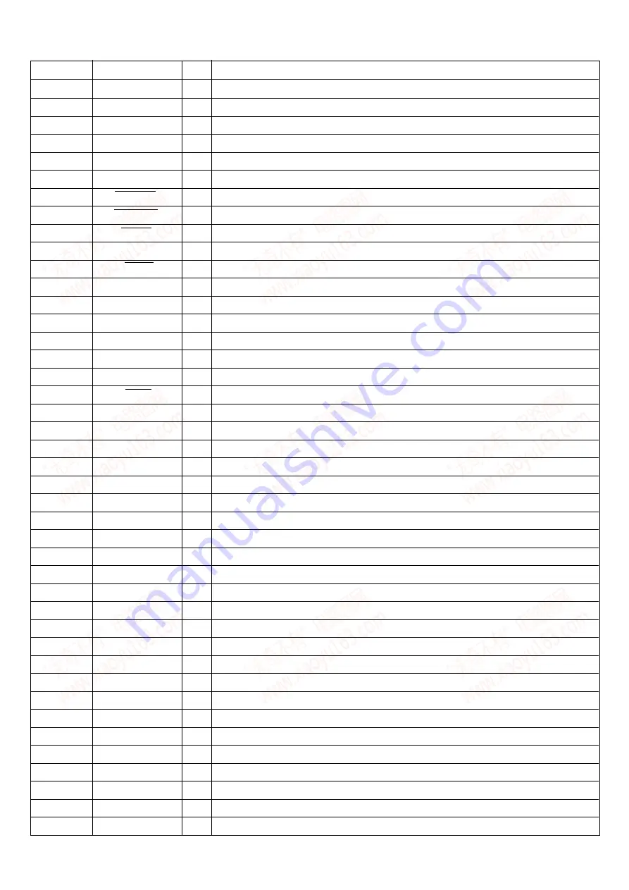
1
O-COCK
O
CD control Q code clock signal output.
2
O-RWC
O
CD control command LAT signal output.
3
O-CDIN
O
CD control command data signal output.
4
I-WRQ
I
CD control SCOR signal input.
5
I-DRF
I
CD control focus OK input.
6
I-SQOUT
I
CD control Q code input.
7
ECO-LED
O
Not used.
8
O-MOTOR
O
Motor control output.
9
O-SOL
O
Cassette play control signal output.
10
O-CLOCK_SHIFT
O
Clock shift output for micro-computer when using tuner.
11
I-RESET
I
Reset input for micro-computer.
12
NC
–
Not connected.
13
O-DECK
O
Deck control output.
14
VSS1
–
Connect to GND.
15
XIN
–
Main clock input 9.43MHz.
16
XOUT
–
Main clock output 9.43MHz.
17
VDD1
–
Digital power supply pin.
18
I-HOLD
I
Hold input.
19
I-VOL
I
Volume control input.
20
RWSWF
–
Not used.
21
I-SW-TP
I
Deck mechanism SW AD input.
22, 23
I-KEY2, I-KEY1
I
Key AD input 2, 1.
24
I-CDTSW
I
CD mecha switch input.
25
I-RDS_SIG
I
Not used.
26
I-AS
I
Cassette deck auto stop switch signal input.
27
DRV-MUTE
–
Not used.
28
I-RDCL
I
Not used.
29
I-RMC
I
System remote control signal input.
–
Not used.
–
Not used.
–
Not used.
VFD driver control data signal output.
VFD driver control data signal output.
–
Digital power supply pin.
VFD driver control data signal output.
51
VEE
–
Connect to –VFL through a resister.
52 ~ 66
O-P6 ~ O-P20
O
VFD driver control data signal output.
67
I-FMW
I
FM selection initialisation resistor connect.
68
I-LW
I
LM selection initialisation resistor connect.
69
NC
–
Not used.
70
I-AM10K
–
AM(10k) selection initialisation resistor connect.
71
I-RDS
I
Not used.
Pin No.
Pin Name
I/O
Description
IC, LC876748A-5Z32
www. xiaoyu163. com
QQ 376315150
9
9
2
8
9
4
2
9
8
TEL 13942296513
9
9
2
8
9
4
2
9
8
0
5
1
5
1
3
6
7
3
Q
Q
TEL 13942296513 QQ 376315150 892498299
TEL 13942296513 QQ 376315150 892498299


