background image

– 15 –

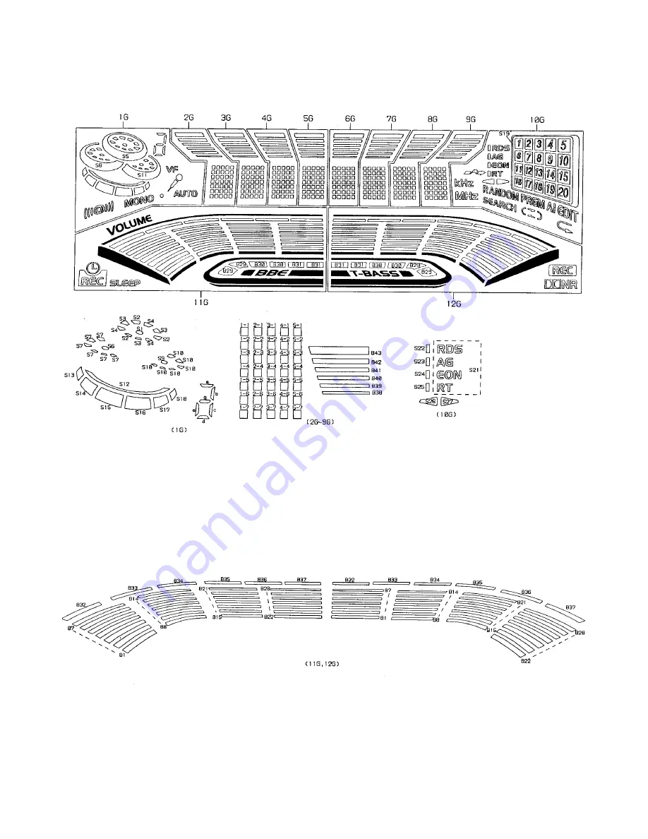
FL (BJ741GK) GRID ASSIGNMENT / ANODE CONNECTION

GRID  ASSIGNMENT

Summary of Contents for XH-N5

Page 1: ...H S M Code No 09 003 424 7R1 R E V I S I O N This Service Manual is the Revision Publishing and replaces Simple Manual S M Code No 09 99C 424 7T1 If requiring information about the CD mechanism see Service Manual of AZG 1 S M Code No 09 001 335 3N6 XH N5 SPEAKER SYSTEM CD CASSEIVER REMOTE CONTROLLER CX AN5 SX WAN5 RC AAS02 ...

Page 2: ...A D 22 SCHEMATIC DIAGRAM 4 OPERATE KEY MIC LED A D 23 WIRING 4 AMP 24 SCHEMATIC DIAGRAM 5 AMP 25 WIRING 5 VIDEO I O VIDEO JACK VIDEO 3 26 SCHEMATIC DIAGRAM 6 VIDEO I O VIDEO JACK VIDEO 3 CONNECT3 3 27 WIRING 6 TUNER 28 SCHEMATIC DIAGRAM 7 TUNER 29 WIRING 7 PT 30 SCHEMATIC DIAGRAM 8 PT 31 WIRING 8 DECK DECK MOTOR HEAD 32 IC BLOCK DIAGRAM 33 38 IC DESCRIPTION 39 40 ADJUSTMENT DECK FRONT TUNER 41 43 ...

Page 3: ...ms PHONES stereo jack accepts headphones of 32 ohms or more SPECIFICATIONS Cassette deck section Track format 4 tracks 2 channels stereo Frequency response 50 Hz 15000 Hz Recording system AC bias Heads Deck 1 Playback head x 1 Deck 2 Recording Playback head x 1 erase head x 1 Compact disc player section Laser Semiconductor laser λ 780 nm D A converter 1 bit dual Signal to noise ratio 85 dB 1 kHz 0...

Page 4: ...fiés peut entraîner une dangereuse exposition aux radiations ADVARSEL Usynlig laserståling ved åbning når sikkerhedsafbrydereer ude af funktion Undgå udsættelse for stråling This Compact Disc player is classified as a CLASS 1 LASER product The CLASS 1 LASER PRODUCT label is located on the rear exterior This set employs laser Therefore be sure to follow carefully the instructions below when servici...

Page 5: ...in power 2 2 2 2 2 Confirm that the main power is turned on and the HOLD terminal of the MICROCOMPUTER keeps the H level or not 3 3 3 3 3 When the HOLD terminal is L level the abnormality detection circuit is judged to be working correctly and the MICROCOMPUTER is judged to be good 1 Forced discharge of electrolytic capacitor of power supply block When repair is going to be attempted in the set th...

Page 6: ... ends of the electrolytic capacitor C113 that is connected to VDD of the MICROCOMPUTER with tweezers 3 3 3 3 3 Connect the AC power cord again If the MICROCOMPUTER returns to the normal operation the MICROCOMPUTER is good Note The reference number or MICROCOMPUTER pin number of transistor Q110 and electrolytic capacitor C113 can change depending on the models Be sure to check the reference numbers...

Page 7: ...ISASSEMBLING PROCEDURE 3 Remove the 4 screws Ex2 Fx2 from both sides 1 Remove the 19 screws Ax11 Bx8 and remove the CABI STEEL 2 Remove the 3 screws from the bottom of the unit A A A A A A A A A A A B B B B B B CABI STEEL B B E F E F ...

Page 8: ...he AZG 1 8 Remove the 2 screws and remove the AZG 1 from the CHAS 3CD The AZG 1 can be repaired while the power is on by using the jig introduced in the Service Technical Information SI 98 028 1 Procedure Connect the jig as shown below CD service position C C C C D C C C C C CABI REAR ASSY C C C D C C C C C C PANEL REAR CD CHAS 3CD CHAS 3CD AZG 1 PWB CONNECT CONNECT C B ...

Page 9: ...87 012 368 080 C CAP S 0 1 50 F C9 87 016 658 090 CAP E 4700 35 SMG C10 87 016 658 090 CAP E 4700 35 SMG C21 87 010 385 080 CAP ELECT 220 25V C22 87 010 385 080 CAP ELECT 220 25V C23 87 010 247 080 CAP ELECT 100 50V C24 87 010 247 080 CAP ELECT 100 50V C25 87 010 430 080 CAP ELECT 100 63 C26 87 010 263 080 CAP ELECT 100 10V C29 87 010 247 080 CAP ELECT 100 50V C30 87 010 235 080 CAP E 470 16 SME C...

Page 10: ...1 25 C678 87 010 196 080 CHIP CAPACITOR 0 1 25 C680 87 010 196 080 CHIP CAPACITOR 0 1 25 C681 87 010 197 080 CAP CHIP 0 01 DM C701 87 010 263 080 CAP ELECT 100 10V C702 87 010 196 080 CHIP CAPACITOR 0 1 25 C703 87 010 319 080 C CAP S 56P 50 CH C704 87 010 319 080 C CAP S 56P 50 CH C705 87 012 393 080 C CAP S 0 22 16 R K C706 87 010 197 080 CAP CHIP 0 01 DM C707 87 010 180 080 C CER 1500P C708 87 0...

Page 11: ...178 080 C CAP S 1000P 50 K B CN205 87 099 564 010 CONN 4P TUC P4P B1 CN206 87 099 564 010 CONN 4P TUC P4P B1 CN207 87 099 564 010 CONN 4P TUC P4P B1 CN208 87 099 564 010 CONN 4P TUC P4P B1 CN302 87 A60 163 010 CONN 15P H FE CN303 87 A60 619 010 CONN 2P V 2MM JMT LED201 87 A40 317 080 LED SLR 342VCT31 RED LED202 87 A40 317 080 LED SLR 342VCT31 RED LED203 87 A40 317 080 LED SLR 342VCT31 RED LED204 8...

Page 12: ...594 010 CONN 17P TUC P17X B1 J901 87 A61 236 010 JACK PIN 3P Y R W J902 87 A61 236 010 JACK PIN 3P Y R W J903 87 A61 236 010 JACK PIN 3P Y R W J904 87 A61 236 010 JACK PIN 3P Y R W J905 87 A61 236 010 JACK PIN 3P Y R W VIDEO 3 C B C951 87 010 196 080 CHIP CAPACITOR 0 1 25 C952 87 010 196 080 CHIP CAPACITOR 0 1 25 C953 87 010 188 080 CAP CHIP 6800P C954 87 010 188 080 CAP CHIP 6800P CN901 87 A60 13...

Page 13: ... U 0 047 16 C771 87 010 383 080 CAP ELECT 33 25V C772 87 010 829 020 CAP U 0 047 16 C773 87 010 196 020 CHIP CAPACITOR 0 1 25 C774 87 010 263 080 CAP ELECT 100 10V C775 87 010 404 080 CAP ELECT 4 7 50V C776 87 012 286 020 CAP U 0 01 25 C777 87 010 400 080 CAP ELECT 0 47 50V C778 87 010 401 080 CAP ELECT 1 50V C779 87 010 401 080 CAP ELECT 1 50V C780 87 010 196 020 CHIP CAPACITOR 0 1 25 C781 87 010...

Page 14: ...of resistor Chip resistor Wattage Type Tolerance 1 16W 1 10W 1 8W 1608 2125 3216 5 5 5 CJ CJ CJ Form L W t 1 6 0 8 0 45 2 1 25 0 45 3 2 1 6 108 118 128 A A CHIP RESISTOR PART CODE 0 55 Resistor Code Dimensions mm Symbol 1 16W 1005 5 CJ 1 0 0 5 0 35 104 L t W B C E 2SA1235 2SC3052 2SC3326 CMBT5401 CMBT5551 DTA123EKA KTA1298 RT1N141C RT1P141C RT1P144C RT1P441C RT1N144C G D S 2SK2158 G D S 2SK2937 ...

Page 15: ... 15 FL BJ741GK GRID ASSIGNMENT ANODE CONNECTION GRID ASSIGNMENT ...

Page 16: ... 16 ANODE CONNECTION ...

Page 17: ...WIRING 1 MAIN 17 10 11 12 13 14 15 16 17 18 19 20 21 22 23 24 A B C D E F G H I J K L M N O P Q R S T U 1 2 3 4 5 6 7 8 9 25 26 27 28 29 30 31 32 ...

Page 18: ... 18 SCHEMATIC DIAGRAM 1 MAIN 1 2 FUNCTION BBE DSP ECHO CONNECT1 3 ...

Page 19: ... 19 SCHEMATIC DIAGRAM 2 MAIN 2 2 DECK ...

Page 20: ...WIRING 2 FRONT CONNECT 20 10 11 12 13 14 15 16 17 18 19 20 21 22 23 24 A B C D E F G H I J K L M N O P Q R S T U 1 2 3 4 5 6 7 8 9 25 26 27 28 29 30 31 32 ...

Page 21: ... 21 SCHEMATIC DIAGRAM 3 FRONT DECK DECK MOTOR CONNECT2 3 ...

Page 22: ...WIRING 3 OPERATE KEY MIC LED A LED B LED C LED D 22 10 11 12 13 14 15 16 17 18 19 20 21 22 23 24 A B C D E F G H I J K L M N O P Q R S T U 1 2 3 4 5 6 7 8 9 25 26 27 28 29 30 31 32 ...

Page 23: ... 23 SCHEMATIC DIAGRAM 4 OPERATE KEY MIC LED A LED B LED C LED D ...

Page 24: ...WIRING 4 AMP 24 10 11 12 13 14 15 16 17 18 19 20 21 22 23 24 A B C D E F G H I J K L M N O P Q R S T U 1 2 3 4 5 6 7 8 9 25 26 27 28 29 30 31 32 ...

Page 25: ... 25 SCHEMATIC DIAGRAM 5 AMP AMP C B ...

Page 26: ...WIRING 5 VIDEO I O VIDEO JACK VIDEO 3 26 10 11 12 13 14 15 16 17 18 19 20 21 22 23 24 A B C D E F G H I J K L M N O P Q R S T U 1 2 3 4 5 6 7 8 9 25 26 27 28 29 30 31 32 ...

Page 27: ... 27 SCHEMATIC DIAGRAM 6 VIDEO I O VIDEO JACK VIDEO 3 CONNECT 3 3 ...

Page 28: ... 29 SCHEMATIC DIAGRAM 7 TUNER ...

Page 29: ...WIRING 7 PT VOLTAGE SEL SW 30 10 11 12 13 14 15 16 17 18 19 20 21 22 23 24 A B C D E F G H I J K L M N O P Q R S T U 1 2 3 4 5 6 7 8 9 25 26 27 28 29 30 31 32 ...

Page 30: ... 31 SCHEMATIC DIAGRAM 8 PT VOLTAGE SEL SW ...

Page 31: ...WIRING 8 DECK DECK MOTOR HEAD 32 1 2 3 4 5 6 7 8 9 10 11 12 13 14 15 A B C D E F G H I J K L M N O P Q R S T U ...

Page 32: ... 33 IC BLOCK DIAGRAM IC BU4052BCF IC BA7625 ...

Page 33: ... 34 IC BU4094BCF IC BA7762AFS ...

Page 34: ... 35 IC M62445AFP IC SPS 442 1 F ...

Page 35: ... 36 IC BA3880FS IC LC72131D ...

Page 36: ... 37 IC BA3835F IC LA1837NL ...

Page 37: ... 38 IC BU2099FV IC BU9262AFS ...

Page 38: ... 25 I SPEANA I A D input for spectrum analyzer display 26 I RDS SG MS I RDS data input Not used MS detect 27 I TM BASE I Time base input for clock 28 I RDS CK I WRQ I RDS clock input Not used CD WRQ input 29 I REM I System remote control signal input 30 41 G12 G1 O FL grid output G12 G1 42 45 P41 P38 O FL segment output P41 P38 46 VDD3 Power supply input 47 P37 O FL segment output P37 48 P36 O SPE...

Page 39: ...input 73 84 P13 P2 O FL segment output P8 P1 85 O KEY SCAN O Switch scan timing output 86 MOTOR O DECK MOTOR ON OFF output 87 O POWER O System power supply ON OFF output 88 SOL2 O DECK2 solenoid output 89 VSS2 GND 90 VDD2 Power supply input 91 DISH RVS O CD turntable reverse rotation output 92 DISH FWD O CD turntable forward rotation output 93 OPEN O CD tray open output 94 CLOSE O CD tray close ou...

Page 40: ...FRONT 1 IC303 SFR351 SFR352 L351 L302 L301 1 IC601 TP3 LCH TP4 RCH GND TP1 LCH TP2 RCH GND MAIN C B A 1 2 3 4 5 6 5 5 R DECK C B CON1 SFR1 1 REV FWD DECK R P E HEAD 2 2 FL101 FRONT C B B IC601 1 L101 TP11 GND TP10 K SCAN 7 C101 ...

Page 41: ... that the output level at TP3 TP4 is 280mV 3dB 5 REC PB Frequency Response Adjustment Settings Test tape TTA 602 NORMAL Test point TP3 Lch TP4 Rch Input signal 1kHz 10kHz 20VU Adjustment location SFR351 Lch SFR352 Rch Method Apply a 1kHz signal and REC mode Then adjust OSC attenuator so that the output level at the TP3 TP4 becomes 20VU Record and play back the 1kHz and 10kHz signals and adjust SFR...

Page 42: ...test point is more than 0 5V 6 FM Tracking Check Settings Test point TP8 Lch TP9 Rch Method Set to FM 98 0MHz and check that the test point is less than 9dBµV 7 DC Balance Mono Distortion Adjustment Settings Test point TP3 TP4 DC balance Adjustment location L771 Input level 60dBµV Method Set to FM 98 0MHz and adjust L771 so that the voltage between TP3 and TP4 becomes 0V 0 04V Next check that the ...

Page 43: ... 33 15 16 17 17 18 19 20 21 23 24 26 27 28 30 31 55 32 AZG 1 CHAS 3CD 34 56 35 61 63 36 37 38 F F C J I J J J I F F F F A A H G H A A A A F F F F F F F F F F F B B A A A B A B A A A A A A E E F A D F F F F D F 39 40 41 42 43 44 60 65 45 46 VOL SELECTOR ASSY 45 47 48 49 58 g 50 51 51 52 53 54 HT SINK 6ZM 1 PT 29 22 57 a a b b c c d d g e f k j j k f e K ...

Page 44: ...mbol Color Basic color symbol Color B Black C Cream D Orange G Green H Gray L Blue LT Transparent Blue N Gold P Pink R Red S Silver ST Titan Silver T Brown V Violet W White WT Transparent White Y Yellow YT Transparent Yellow LM Metallic Blue LL Light Blue GT Transparent Green LD Dark Blue DT Transparent Orange GM Metallic Green YM Metallic Yellow DM Metallic Orange 41 86 LB7 694 010 AC CORD SET KE...

Page 45: ... 46 TAPE MECHANISM PARTS LIST 1 2 6ZL 1 A1 a 6ZM 4 R3 P C B a 1 2 3 4 5 BASE MECHA 6 7 8 9 10 11 12 13 B A C C ...

Page 46: ... 86 ZL1 202 010 FRAME CAS 5 86 ZL1 209 010 LEVER LOCK 6 86 ZL1 214 010 SPR P CAS 7 86 ZL1 211 010 ARM CLAMP 8 86 ZL1 206 010 GEAR TRAY 9 86 ZL1 213 010 SPR E CLAMP 10 86 ZL1 208 010 LEVER SW 11 86 ZL1 207 010 GEAR PULLEY 12 86 ZL1 212 010 BELT L 13 86 ZL1 210 010 PULLEY MOT A 83 ZG3 217 010 S SCREW GEAR D B 87 251 072 410 U 2 6 5 C 87 067 660 010 BVT2 3 8 W 0 SL0T BLK ...

Page 47: ...19 4 6 20 5 21 21 24 25 26 29 29 27 28 3 2 RELAY C B HLDR WIRE 3 SHAFT REEL 18 B B A A B A B 31 38 39 40 32 34 33 35 43 45 41 41 37 44 50 DECK C B SOL2 49 47 48 46 C C E 36 42 52 51 55 CUSH G DIA 3 7 9 3 2 PLATE SHLD SH 1 75 3 6 0 5 SLT SH 1 63 3 2 0 5 SLT 53 54 22 8 22 8 C C C D D G H F ...

Page 48: ... LVR ASSY PINCH R3 28 82 ZM1 259 110 SPR T PINCH R 29 82 ZM1 240 110 LVR REC 30 82 ZM1 298 010 SPR P EARTH 31 82 ZM1 255 310 SPR E LVR DIR 32 82 ZM1 221 110 GEAR CAM 33 82 ZM1 227 210 LVR TRIG 34 82 ZM1 224 410 LVR FR 35 86 ZM4 201 010 SPR E TRIG 3 36 82 ZM1 239 010 CAPSTAN 2 2 41 7 37 82 ZM1 223 010 GEAR PLAY 38 82 ZM1 322 010 SPR T FR 60 39 82 ZM1 220 210 GEAR IDLER 40 82 ZM1 316 010 RING MAGNET...

Page 49: ...rning to clockwise direction until click sound comes out Remove the grill frame and four pieces of rubber caps by pulling out with a flat bladed screwdriver Remove the screws from hole where installed rubber caps Insert a flat bladed screwdriver into the position indicated by the arrows and remove the panel Re move the screws of each speaker unit and then remove the speaker units TOOLS 1 Plastic h...

Page 50: ...A 6 8A MS1 602 010 SPKR W 200 7 8A MS4 603 010 SPKR M 120 8 88 NS3 605 010 CAP 9 88 MS1 610 010 CORD SPKR 10 88 NS5 611 010 CORD SPKR B L 11 88 NS5 605 010 SPKR T 60 12 8A MS4 015 010 PANEL TW 60 ACCESSORIES PACKAGE LIST DESCRIPTION REF NO KANRI NO PART NO 1 8A MT4 902 010 IB LH ESP M 2 87 006 225 010 AM LOOP ANT NC2 3 87 043 115 010 ANT FEEDER FM 4 87 099 789 010 PLUG ADPTR IR44 5 8A MT4 702 010 ...

Page 51: ...2 11 IKENOHATA 1 CHOME TAITO KU TOKYO 110 JAPAN TEL 03 3827 3111 Printed in Singapore 9820527 0251431 ...

Reviews: