B1-1
2
UP TO
RELEASE
Front Cabinet
TV/VCR Block
1
1
Main PWB Holder
VCR Block
Main PWB
DISASSEMBLY INSTRUCTIONS
1. REMOVAL OF MECHANICAL PARTS
AND P.W. Boards
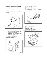
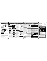
1-1: BACK CABINET (Refer to Fig. 1-1)
1.
2.
3.
4.
5.
Remove the 2 screws
1
.
Remove the 2 screws
2
.
Remove the 2 screws
3
which are used for holding the
Back Cabinet.
Remove the AC cord from the AC cord hook
4
.
Remove the Back Cabinet in the direction of arrow.
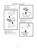
1-3: TV/VCR BLOCK (Refer to Fig. 1-3)
1.
2.
3.
4.
Remove the 2 screws
1
.
Disconnect the following connectors:
(CP351, CP757, CP302, CP401, CP501 and CP502).
Unlock the support
2
.
Remove the TV/VCR Block in the direction of arrow.
Fig. 1-3
1-4: MAIN PWB (Refer to Fig. 1-4)
1.
2.
3.
4.
5.
6.
Remove the screw
1
.
Remove the Main PWB Holder.
Remove the 2 screws
2
.
Remove the 3 screws
3
.
Disconnect the following connectors:
(CP810 and CP820).
Remove the Main PWB in the direction of arrow.
Fig. 1-1
1-2: CRT PWB (Refer to Fig. 1-2)
CAUTION: BEFORE REMOVING THE ANODE CAP,
DISCHARGE ELECTRICITY BECAUSE IT
CONTAINS HIGH VOLTAGE.
BEFORE ATTEMPTING TO REMOVE OR
REPAIR ANY PWB, UNPLUG THE POWER
CORD FROM THE AC SOURCE.
Fig. 1-2
CRT PWB
Front Cabinet
Fig. 1-4
Front Cabinet
1
1
2
2
3
3
4
Back Cabinet
1.
2.
3.
Remove the Anode Cap.
(Refer to REMOVAL OF ANODE CAP)
Disconnect the following connectors:
(CP801 and CP850).
Remove the CRT PWB in the direction of arrow.
1
2
3
2
3 3


