4
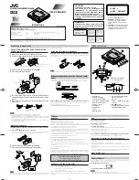
DISASSEMBLY INSTRUCTIONS
1. Removing the PANEL, BOT
Remove the screw
A
*
1 and screw
B
*
6, and remove the PANEL, BOT in the direction of the arrow.
*
When attaching the PANEL, BOT, set the KNOB, SL HOLD.
2. Removing the MAIN C.B
1)
Connect the shorting lands of the pickup by a solder bridge.
*
When the MAIN C.B is attached, remove the solder bridge.
2)
Remove the FFC of the CN300, CN700 and CN100.
3)
Remove the screw
A
*
3 and screw
B
*
1.
4)
Remove the battery lid and remove the MAIN C.B, while being careful of the BAT-C.
*
When the MAIN C.B is attached, be careful of the BAT-C.
B
A
A
A
BAT-C
MAIN C.B
HINGE ASSY, BATT
* The BAT-C is attached under
the HINGE ASSY, BATT
B
B
B
B
B
B
A
PANEL, BOT
KNOB, SL HOLD
Summary of Contents for AM-HX50
Page 9: ...10 9 BLOCK DIAGRAM 7 27 EFMIN MOE MCAS MRAS MWE X200 16 93MHZ 72 S300 OPEN CLOSE P CONT ...
Page 10: ...12 11 WIRING 1 MAIN 14 13 12 11 10 9 8 7 6 5 4 3 2 1 A B C D E F G H I J ...
Page 11: ...14 13 1 2 3 4 5 6 7 8 9 10 11 12 13 14 A B C D E F G H I J ...
Page 12: ...16 15 SCHEMATIC DIAGRAM ...
Page 28: ...32 IC BLOCK DIAGRAM IC TA2131FL IC S 93C46AMFN IC TC7W74FU ...
Page 32: ...931196 Printed in Singapore 2 11 IKENOHATA1 CHOME TAITO KU TOKYO 110 JAPAN TEL 03 3827 3111 ...


