THIS EQUIPMENT COMPLIES WITH FCC REQUIREMENTS
PURSUANT SUBPART J OF PART-15
This device complies with Part 15 of the FCC Rules. Operation is subject to the following two
conditions: (1) this device may not cause harmful interference, and (2) this device must accept any
interference received, including interference that may cause undesired operation.
WARNING: Changes or modifications to this product not expressly approved by the party responsible
for compliance could void the user’s authority to operate this equipment.
NOTE: This equipment has been tested and found to comply with the limits for a digital device,
pursuant to Part 15 of the FCC Rules. These limits are designed to provide reasonable protection
against harmful interference in a residential installation. This equipment generates, uses, and can
radiate radio frequency energy and, if not installed and used in accordance with the instructions, may
cause harmful interference to radio communications. However, there is no guarantee that
interference will not occur in a particular installation. If this equipment does cause harmful
interference to radio or television reception, which can be determined by turning the equipment off
and on, the user is encouraged to try to correct the interference by one or more of the following
measures:
- Reorient or relocate the receiving antenna.
- Increase the separation between the equipment and receiver.
- Connect the equipment into an outlet on a circuit different from that to which the receiver is
connected.
- Consult the dealer or an experienced radio TV technician for help.
This equipment complies with FCC radiation exposure limits set forth for an uncontrolled
environment. This equipment should be installed and operated with minimum distance 20cm between
the radiator and your body. This Transceiver must not be co-located or operating in conjunction with
any other antenna or Transceiver.
Disclaimer
The information within this document has been carefully checked and is believed to
be entirely reliable. However, no responsibility is assumed for inaccuracies. Lathem
Time Corp. reserves the right to make changes to any products herein to improve
reliability, function, or design.
Trademark
AirTime, Lathem and the Lathem logo are registered trademarks of Lathem Time
Corporation. Other product names mentioned in this manual may be trademarks of their
respective companies and are hereby acknowledged.
WARNING: Changes or modifications to this product not expressly approved by the party
responsible for compliance could void the user’s authority to operate this equipment.
Copyright © 2009 Lathem Time Corporation. All rights reserved.
Lathem Inc
200 Selig Drive SW
Atlanta, GA 30336
www.lathem.com
Other AirTime Products
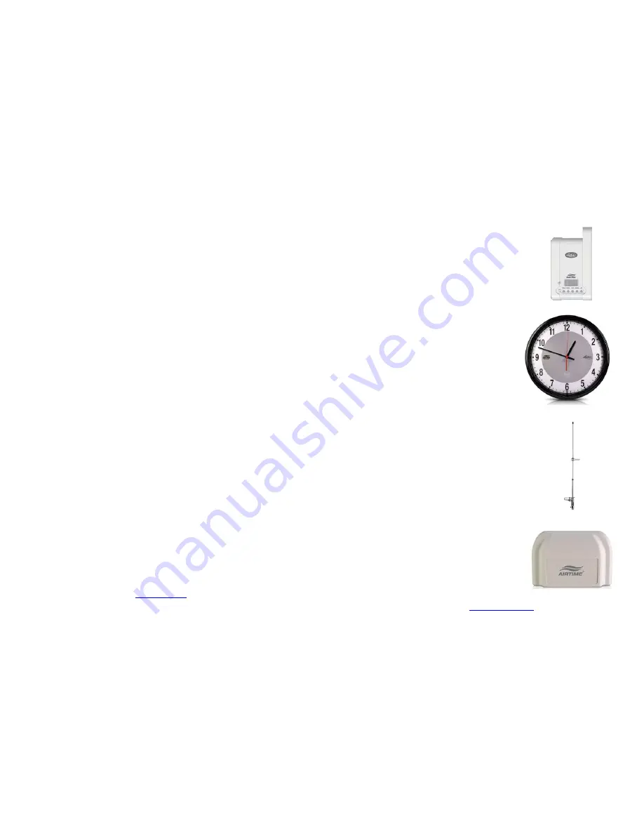
ATX
Mini Transceiver capable of
receiving the WWVB signal and
transmitting exact time in smaller
facilities
AT12RPS
Solar Powered
12” Analog
Wireless
Wall
Clock
AT-ANTOD
Outdoor Antenna for maximum
coverage with the ATX6 or the AT20WT
AT-MSX
AirTime receiver that accepts the AirTime signals from
an ATX, ATX6 or AT20WT and
corrects Lathem RS485
devices or Intercom systems
via a 12:00AM dry contact
closure
Contact your distributer or visit
www.lathem.com
for more information

