


ATDDC4 Series Installation & User’s Guide
Page 10
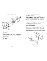
5.
Slide the circuit board
assemblies in partially and secure the
required wiring.
6.
Slide the circuit board assemblies in fully, then slide the front
lenses into place.
Note: the inside of the lens has a paper
backing
which should not be removed
. The end with wider
paper should go to the right.
Replace the end caps and secure
each with two Phillips head screws.
ATDDC4 Series Installation & User’s Guide
Page 3
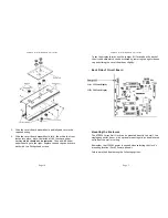
To set the display format, use the jumper (J1) located on the back of
the circuit board which can be accessed by removing the right side end
cap and sliding the circuit board out slightly.
Back Side of Circuit Board
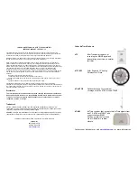
Mounting the Enclosure
The ATDDC4 Series Wall Clock can be mounted directly to a wall, to a
single gang outlet box or, with optional mounting kits, as double-faced
units from the wall or ceiling.
Remember that 120VAC power is needed when selecting the clock’s
mounting location (24vAC Power optional).
Select a method from among the following options:
Jumper J1
On = 12 Hour display
Off = 24 Hour display


