AirSpeed 2900 gNB 5G OD Installation Guide
© Copyright
Airspan Networks Ltd.,
2021
P/N DUG01085
Rev. A, Nov 2021
25
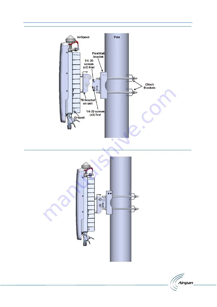
Figure 8: Pole Mounting Assembly
The following displays the AirSpeed 2900 mounted on a pole.
Figure 9: Mounted on Pole
Page 1: ...AIRSPEED 2900 INSTALLATION GUIDE 5G Outdoor gNB Installation Guide Document Part Number DUG01085 Document Revision A Published November 2021 ...
Page 2: ...of whatever nature in respect of these documents including without limitation the accuracy or completeness of any information facts and or opinions contained therein No responsibility is assumed by Airspan Networks Ltd for the use of the documents nor for the rights of third parties which may be effected in any way by the use thereof The provision of these documents and the documents themselves do...
Page 3: ...htning Protection 8 Outdoor Ethernet Cabling 9 DECLARATION OF CONFORMITY 9 GPS Compliance 12 Maximum Output TX Total Power 12 Voltage and Amperage 12 Antenna System 13 Integrated Antenna Parameters 13 About this Document 14 Purpose 14 Intended Audience 14 Document Conventions 14 Related Reading 15 Customer Care Help Desk 15 Airspan Encourages Comments 15 1 Getting Started 16 1 1 AirSpeed 2900 Inst...
Page 4: ... 19 Figure 3 AirSpeed 2900 Bottom Ports 20 Figure 4 Environmental and Standard Compliance 21 Figure 5 Tilt bracket Assembly 23 Figure 6 Position on Pole 24 Figure 7 Mounting Bracket on Pole 24 Figure 8 Pole Mounting Assembly 25 Figure 9 Mounted on Pole 25 Figure 10 AirSpeed on Wall 26 Figure 11 Tilt Adjustment 27 Figure 12 Ground Connection 28 Figure 13 Pre assembled Single Mode LC Cable 30 Figure...
Page 5: ...eed 2900 gNB Maximum Output TX Total Power 12 Table 2 Voltage Amperage Draws 12 Table 3 Integrated Antenna Parameters 13 Table 4 Typographic Conventions 14 Table 5 Minimum Hardware Requirements 17 Table 6 Parts Kits 18 Table 7 AirSpeed 2900 Physical Dimensions 21 Table 8 System LED Function 29 Table 9 ABBREVIATIONS DEFINITIONS 35 ...
Page 6: ...he Airspan s AirSpeed 2900 gNB 5GB Outdoor unit AirSpeed 2900 is a compact easy to deploy gNB for pole and wall installation This document is intended for qualified personnel with a working knowledge of 5G Revision History Revision Date Summary of Changes Created by Rev 0 1 0 4 November 2021 Initial document draft After comments draft CY MSF Rev A November 2021 Published CY MSF ...
Page 7: ...e is no guarantee that interference will not occur in a particular installation If this equipment does cause harmful interference to radio or television reception which can be determined by turning the equipment on and off the technician is encouraged to try to correct the interference by performing one or more of the following measures Re orientate or relocate the unit Increase separation between...
Page 8: ...ities Failure to do so may void Airspan s product warranty and may expose the end user or the service provider to legal and financial liabilities Airspan and its resellers or distributors are not liable for injury damage or violation of regulations associated with the installation of outdoor units or antennas The device is to be installed in a Restricted Access Location Surge Arrestors and Transie...
Page 9: ... in accordance with the local electrical codes 11 Installation of the AirSpeed 2900 gNB must be contracted to a professional installer 12 The circuit breaker should be easily accessible in case you have to disconnect the device 13 When installed in the final configuration the product must comply with the applicable Safety Standards and regulatory requirements of the country in which it is installe...
Page 10: ...ment must be properly grounded according with NEC and other local safety code requirements Reminder to all the BWA system installers Attention to Section 820 40 of the NEC which provides guidelines for proper grounding and in particular specifies that the cable ground shall be connected to the grounding system of the building as close to the point of cable entry as is practical AirSpeed 2900 gNB i...
Page 11: ...ectors to the same ground point at the base of the tower or a ground bus on the building Use the grounding screws on the antenna bracket and the radio and antenna for terminating the ground wires The AC wall outlet ground must be connected to the same grounding system as the eNodeB Outdoor Ethernet Cabling Ethernet cable connected to should be outdoor grade with UV protection Use shielded out CAT5...
Page 12: ...o Airspan paziņo ka vienība atbilst Direktīvas 2014 53 ES būtiskajām prasībām un citiem attiecīgajiem noteikumiem Lithuanian Šis Airspan pareiškia kad šis įrenginys atitinka esminius Direktyvos 2014 53 ES reikalavimus ir kitas nuostatas Nederlands Airspan verklaart hierbij dat de apparaateenheid voldoet aan de essentiële vereisten en andere relevante bepalingen van richtlijn 2014 53 EU Maltese Haw...
Page 13: ...irspan att denna enhet överensstämmer med de väsentliga egenskapskraven och andra relevanta bestämmelser som anges i direktiv 2014 53 EU Íslenska Airspan lýsir hér með yfir að þessi eining uppfylli grunnkröfur og aðrar kröfur tilskipunar 2014 53 ESB Norsk Airspan erklærer herved at utstyrsenheten oppfyller grunnleggende krav og andre relevante krav i direktiv 2014 53 EU Român Airspan declarăm pe p...
Page 14: ... 3 Radiated RF EM Field Immunity Test EN 61000 4 4 Electrical Fast Transient Burst Test EN 61000 4 6 Conducted Immunity EN 61000 4 8 Magnetic Field Immunity A GPS is recommended for synchronizing the unit An optional GPS Lightning Surge protector is available from Airspan when installing the GPS antenna in a remote location for lightning prone deployments Maximum Output TX Total Power Table 1 AirS...
Page 15: ... front mount integrated antenna supports two carriers 2x 2T2R External antenna 4 ports to two external antennas Each antenna can serve a 2T2R sector in different directions Hybrid single sector via the integrated antenna and a second sector via the external antenna Integrated Antenna Parameters Table 3 Integrated Antenna Parameters Polarization Elevation BW AZ Beamwidth Gain Dual Slant 45 8 65 17d...
Page 16: ...llowing typographic conventions Table 4 Typographic Conventions Convention Element Blue underlined text Cross reference links Bold text Keyboard buttons and GUI elements Command Command names or phrases Computer output Text displayed by the computer Hyperlinks Website and e mail addresses Danger Signifies a hazardous situation if not avoided will cause death or serious injury Describes how to avoi...
Page 17: ...stomer Care Help Desk Once you submit your issue the system generates a new issue and sends an issue number for your reference The system uses this issue number to categorize and store e mails under the appropriate issue To help Customer Care Help Desk identify your issue include the issue number and your Customer Care Helpdesk account details in all further communications Main Operations Airspan ...
Page 18: ...P N DUG01085 Rev A Nov 2021 16 1 Getting Started 1 1 AirSpeed 2900 Installation Checklist Plan the installation of the AirSpeed 2900 by using the Installation Checklist which you can find as a removable job aid in Appendix A for this guide Figure 1 AirSpeed 2900 with GPS attached ...
Page 19: ... Installation Requirements 2 2 1 Verify the Tools Table 5 Minimum Hardware Requirements Tool Use 10 mm or 13 32 inch wrench for securing the M6x16 Hex bolts to assemble the Tilt bracket to the AirSpeed back 7 16 inch wrench For securing Tilt bracket to the Pole bracket with the 1 4 20 bolts 1 2 inch wrench For securing the 5 16 18 threaded rods Airspan does not provide screws and wall anchors for ...
Page 20: ... 3 7 GHz n48 AS29 N48 DSC1 AirSpeed 2900 n48 Integrated Antenna DC Octis connector 48V DC Connector for DC connection included SFP Connector for SFP connection Octis RJ45 Ethernet Connector Connector for Ethernet RJ45 AirSpeed 2900 universal pole and wall Mounting KIT AS103 U PMK 1 AirSpeed 2900 mounting kit for 50 150 mm 2 6 to 4 3 inch pole including 1 Pole mount Bracket Base kit including Tilt ...
Page 21: ...erational Voltage Range 40 5V to 57V DC 2 2 4 Connections The following diagrams display the connections on the top and bottom panels of the AirSpeed 2900 The unit requires a secure ground connection and a grounding screw fitted with a flat washer and lock washer is provided on the back and clearly marked with the universal ground symbol Figure 2 AirSpeed 2900 Top Ports with integrated antenna ...
Page 22: ...AirSpeed 2900 gNB 5G OD Installation Guide Copyright Airspan Networks Ltd 2021 P N DUG01085 Rev A Nov 2021 20 Figure 3 AirSpeed 2900 Bottom Ports ...
Page 23: ...mental Figure 4 Environmental and Standard Compliance Parameter Details IP rating Main unit IP67 Antenna IP65 Operating Temperature range 40 C to 55 C 40 F to 140 F Operating humidity 5 95 Public transportation temperature 40 C to 70 C 40 F to 158 F Public transportation humidity Up to 95 Ultraviolet A UVA Ultraviolet B UVB Rays According to GR 2873 CORE and ASTM G154 Wind Resistance 100 mph susta...
Page 24: ...ective dust cap from the GPS antenna jack prior to mounting on the AirSpeed 2900 2 Align the GPS jack with the plug attached to the top panel on the AirSpeed 2900 and screw on 3 1 1 Weather proofing the GPS Antenna Connection Weather proofing of the GPS antenna connection is required This is done with a layer of self amalgamating tape followed by an over layer of PVC tape Verify the RF connector i...
Page 25: ...the pole mounting procedure 1 Remove the upper two 2 screws from the Pole Wall bracket and set them aside to be used later Loosen the lower two 2 screws so they protrude from the Pole Wall bracket 2 Select the location on the pole to mount the AirSpeed 2900 mounting bracket 3 Screw the four 4 5 16 18 threaded rods into the threads on the back bracket 4 Allow the threaded rods to protrude through t...
Page 26: ... position the unit so that the lower screws 1 on each side fit into the notched grooves provided on the back bracket pre assembled on the unit and hand tighten Insert the upper 1 4 20 screws washers and nuts supplied and fasten the back bracket to the mounting bracket 10 Carefully align and position the unit so that the screws 1 on each side fit into the notched grooves provided on the Tilt bracke...
Page 27: ...0 gNB 5G OD Installation Guide Copyright Airspan Networks Ltd 2021 P N DUG01085 Rev A Nov 2021 25 Figure 8 Pole Mounting Assembly The following displays the AirSpeed 2900 mounted on a pole Figure 9 Mounted on Pole ...
Page 28: ...ovided and tighten in place 5 Assemble the 2 SEMS screws M6 x 16 into the lower threaded holes on the mounting base bracket do not tighten Wall anchors x4 and necessary hardware are not supplied by Airspan and are the responsibility of the installer Use appropriate wall anchors according to field conditions 6 Carefully align and position the unit so that the screws 1 on each side fit into the notc...
Page 29: ...e There are adjustment slots located on the sides of unit body where it is attached to the Mounting bracket The AirSpeed 2900 unit body has a yield of a maximum tilt of 20 up and 30 down Once the AirSpeed unit is mounted in place and a tilt adjustment is needed 1 Slightly loosen the four 4 bolts on both sides of the mounting bracket 2 Adjust the unit to the required tilt 3 After adjustment to the ...
Page 30: ...FP cable to the AirSpeed 2900 unit Grounding cable Fiber Ethernet cable SFP connector adaptor and DC power cables are not supplied as part of the AirSpeed 2900 and can be ordered separately 4 1 Grounding The AirSpeed 2900 requires a secure ground connection and a grounding screw fitted with a flat washer and lock washer is provided on the back and clearly marked with the universal ground symbol Th...
Page 31: ...ng normal operation There are two 2 LEDs on the unit Backhaul LED indicates if the unit is connected to the network System LED see table below Table 8 System LED Function State Name LED Color LED State Description Powering Up White On Continuously Till running from operational SW image Software loading Startup Green Blinking 3Hz Till SW startup is finished and the product is ready to radiate Norma...
Page 32: ...ed assembly instructions hardware and tool requirements for the proper DC cable assembly used by Airspan products Power Cable Diameter 8 4mm to 9 4mm Wire Size AWG16 to AWG14 Safety Disconnection of power supply When AirSpeed unit is connected directly to wiring a suitably rated and easily accessible circuit breaker shall be incorporated externally to the equipment Power source disconnection is re...
Page 33: ...ng up then lift the clamp handle Figure 15 Open Housing Lock 3 Separate the housing into its component sections Figure 16 Separate into Sections 4 Insert the Gland nut through the other end of the cable Figure 17 Insert Gland Nut 5 Loosen the strap clamp and feed the prepared end of the source power cable into the inner part of the DC connector housing Figure 18 Pass DC Cable Thru ...
Page 34: ...d tighten the 2 screws Verify the wire polarity before securing as shown in figure 19 Figure 19 Power Wire Connection Figure 20 Tightening of Set Screws 7 Tighten the strap clamp screw as shown below Figure 21 Tighten the Strap Clamp 8 Insert into outer housing until click in place align marks for proper alignment Figure 22 Align Marks Click in Place 9 Place the split rubber gland onto the cable ...
Page 35: ...more than 2 2 5 Nm 1 47 1 84 ft lb max Figure 25 Tighten gland Nut 12 Insert the connector into the Power port on the bottom of the chassis Verify that the connector s latch faces the rear of the unit to enable potential unlocking 13 Close the lever and secure the lock by sliding the secondary lock button so that lever can t be lifted Figure 26 Secure Housing Lock When securing the cable verify th...
Page 36: ...this checklist and use it as a job aid After performing check off each task Procedure Action Check If Performed Verify the prerequisites Verify the site requirements Verify the installation requirements Verify the tool requirements Verify the parts kits required AirSpeed 2900 installation Install Tilt bracket on the AirSpeed 2900 Install the GPS antenna on the unit Install the Pole Wall bracket on...
Page 37: ...Decibel A logarithmic unit used to describe a ratio such as power ratio in radio telecommunications dBm An abbreviation for the power ratio in decibels dB of the measured power referenced to one milliwatt mW It is used as a convenient measure of absolute power because of its capability to express both very large and very small values in a short form gNB next generation NodeB OD Outdoor ...