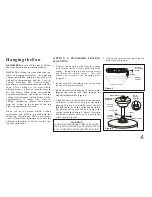
AirPro P2501 Installation Manual Download Page 11

8.

Rubber

washer

Blade
arm

Figure 12

Blade

Screws

Attaching the Fan 
Blades

Step 1 

Attach the blades to the blade arms 

using three screws and rubber washers as 
shown in Figure 12.  Start a screw into the arm, 
do not tighten.  Repeat for the 2 remaining 
screws and washers.

Step 2 

Tighten each screw securely starting 

with the center screw.  Make sure the blade is 
straight.

NOTE:

 Your fan blades are reversible.  Select 

the blade side finish which best accentuates 
your decor.

Fasten the blade assembly to the motor 

using the motor screws that are already pre-
attached in the motor.

Step 3


(Figure 13)

Step 4 

Install an optional light kit if you wish. 

Follow the instructions included with the kit.

Figure 13

Motor

Blade  arm

Blade blancing

deviation 

3. Use the enclosed Blade Balancing Kit if 
the blade wobble is still noticeable.

4. If the blade wobble is still noticeable, 
interchanging two adjacent (side by side) 
blades can redistribute the weight and 
possibly result in smoother operation.

All blades are grouped by weight.  Because 
natural woods very in density, the fan may 
wobble even though the blades are weighed  
equally.

The following procedure should correct 
most fan wobbling problems. Check after 
each step.

1. Check that all blade and blade arm 
screws are secure.

2. Most fan wobbling problems are caused 
when blade levels are unequal. Check this 
level by selecting a point on the ceiling 
above the tip of one of the blades. Measure 
this distance as shown in Figure 14. Rotate 
the fan until the next blade is positioned for 
measurement. Repeat for each blade. The 
distance 

should be equal within 

1/8".

'

Summary of Contents for P2501

Page 1: ...P2501 Ceiling Fan Installation Manual...

Page 2: ...G WILL NOT ASSUME LIABILITY OR RESPONSIBILITY FOR DAMAGES INCLUDING INCIDENTAL OR CONSEQUENTIAL CAUSED BY THE IMPROPER INSTALLATION OR OPERATION OF THE UNIT OR ITS COMPONENT PARTS OR BY THE FAILURE OF...

Page 3: ...Safety Rules Unpacking Your Fan Installing Your Fan Care of Your Fan Troubleshooting Specifications Operating Your Fan 1 2 3 9 10 11 12 Table of Contents...

Page 4: ...hen cleaning the fan or fan blades A dry dust cloth or lightly dampened cloth will be suitable for most cleaning 11 After marking electrical connections spliced conductors should be turned upward and...

Page 5: ...re Balancing kit b Blade bracket attachment hardware 11 screws with lock washers 3 plastic wire connectors 1 Pull chain Blade balancing kit a b c 3 1 2 5 6 4 d 1 2 Mounting plate located inside canopy...

Page 6: ...5 If the canopy touches downrod remove the decorative canopy bottom cover and turn the canopy 180 before attaching the canopy to the mounting plate To hang your fan where there is an existing fixture...

Page 7: ...N 1 STANDARD CEILING MOUNTING 3 Route the wires exiting the top of the fan motor through the canopy and then through the ball downrod assembly Figure 6 4 Align the holes at the bottom of the downrod w...

Page 8: ...te as shown in Fig 9 3 Tighten the two screws on the outlet box securely 4 Carefully life the fan assembly up to the ceiling mounting plate and hang the fan on the hook provided by utilizing one of th...

Page 9: ...the ball downrod assembly is not used 6 Figure 9 Figure 10 Mounting screws supplied with electrical box Ceiling mounting plate UL Listed electrical box 120V Wires Washers WARNING WHEN USING THESTANDA...

Page 10: ...ng screwsfirmly 7 SUPPLYCIRCUIT Ground Conductor Outlet Box Green Ground Lead Ground to Downrod BLACK WHITE WHITE BLACK BLUE GREEN WHITE BLUE BLACK WHITE Figure 11 Diagram indicates optional light kit...

Page 11: ...13 Motor Blade arm Blade blancing deviation 3 Use the enclosed Blade Balancing Kit if the blade wobbleis still noticeable 4 If the blade wobble is still noticeable interchanging two adjacent side by s...

Page 12: ...d settings for warm or cool weather depend on factors such as the room size ceiling height numberof fans andso on The slide switch controls directions forward switch down or reverse switchup Warm weat...

Page 13: ...g the finish The plating is sealed with a lacquer to minimize discoloration or tarnishing Do not use water when cleaning This could damage the motor or the wood or possibly cause an electrical shock 3...

Page 14: ...st each otheror the interiorwall of theswitch housing CAUTION Make suremain power isoff 4 Allowa 24 hour breaking in period Most noiseassociated with anew fan disappearduring this time 5 If usingan op...

Page 15: ...andWattage used by the light kit RPM CFM N W G W C F 52 120 Xx kgs Xx kgs Xxx Xx Xx Xxxx 120 120 Fan Size Speed Volts Amps Watts Low Medium High Specifications 12 2005 Progress Lighting Co 101 Corpor...

Reviews: