


Finishing the
Installation
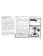
OPTION 1: STANDARD CEILING
MOUNTING
1. Align the locking slots of the ceiling
canopy with the two screws in the
mounting plate. Push up to engage the
slots and turn clockwise to lock in place.
Immediately tighten the two mounting
screws firmly.
2. Install the remaining two mounting
screws into the holes in the canopy and
tighten firmly.
3. You may now proceed to attach the fan
blades.
OPTION 2: CLOSE-TO-CEILING
MOUNTING
1. Carefully unhook the fan from the
mounting plate and align the locking
slots of the ceiling canopy with the two
screws in the mounting plate. Push up to
engage the slots and turn clockwise to
lock in place.Immediately tighten the
two mounting screws firmly.
7.
SUPPLY CIRCUIT
Ground
Conductor
Outlet Box
Green
Ground
Lead
Ground to
Downrod
B
L
A
C
K
W
H
IT
E
W
H
IT
E
B
L
A
C
K
B
L
U
E
G
R
E
E
N
WHITE
BLUE
BLACK
WHITE
Figure 11
Diagram indicates optional light kit wiring.
WARNING
ELECTRICAL DIAGRAMS ARE FOR
REFERENCE ONLY. OPTIONAL USE OF
ANY LIGHT KIT SHALL BE UL LISTED
AND MARKED SUITABLE FOR USE WITH
THIS FAN.
2. Install the remaining two mounting
screws into the holes in the canopy and
tighten firmly.
3. You may now proceed to attach the fan
blades.
WARNING
WHEN USING THE STANDARD
BALL/DOWNROD MOUNTING, THE
TAB IN THE RING AT THE BOTTOM OF
THE MOUNTING PLATE MUST REST IN
THE GROOVE OF THE HANGER BALL.
FAILURE TO PROPERLY SEAT THE TAB
IN THE GROOVE COULD CAUSE
DAMAGE TO WIRING.
WARNING
LOCKING SLOTS OF CEILING CNAOPY
ARE PROVIDED ONLY AS AN AID TO
MOUNTING. DO NOT LEAVE FAN
ASSEMBLY UNATTENED UNTIL ALL
FOUR CNAOPY SCREWS ARE
ENGAGED AND FIRMLY TIGHTENED.


