10
IO-123163 Effective 01-14-2016
1.
Bring airflow up to the maximum CFM possible according to Table
11A-1.
2.
Evacuate refrigeration system to micron level required by outdoor
unit manufacturer.
14. System Charging
An improperly charged system may cause
degradation in system performance and
damage the compressor. After installation
of the coil, refer to the outdoor unit manufacturer for charging
techniques and amount of charge. If outdoor unit manufacturers
charging instructions are unavailable, then refer to instructions
below to charge the system.
CAUTION
!
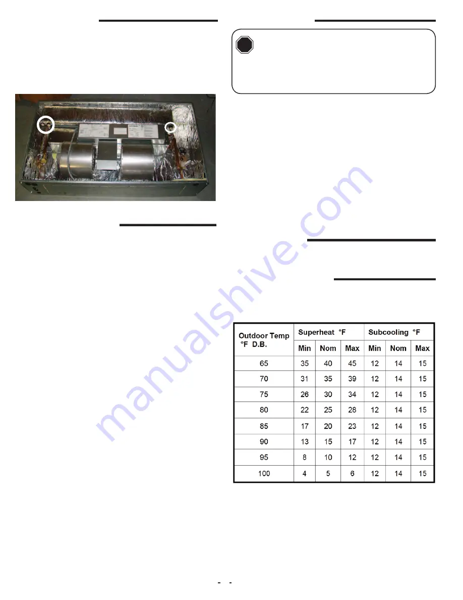
14B . Expansion Valve Coils
Add refrigerant until the subcooling measured at the outdoor unit
liquid line matches the subcooling recommendation of the outdoor
manufacturer (typically 7º – 10º F). If chart is unavailable refer to
Table 14B-1.
Table 14B-1
14A . Flowrator Coils
Add refrigerant until the superheat measured at the outdoor unit
suction/vapor line matches the superheat listed in Table 14B-1.
3.
Release system charge from outdoor unit and call for cooling.
4.
Use outdoor unit equipment manufacturer specific charging charts
if available and make proper charge adjustment based upon outdoor
unit instructions.
5.
If outdoor unit instructions and charts are not available, use Aspen
provided charts. Make certain indoor air temperature is near comfort
level setpoint of 75°F prior to establishing superheat and subcooling
levels.
12. Condensate Drain
1. Select desired condensate drain openings according to air handler
orientation. Both Primary and Secondary outlets can be used.
2. Pipe condensate system using proper PVC fittings.
3. Ensure a minimum 2” trap is installed in the condensate drain.
Locate the trap near to the connection opening on the air handler.
See illustration.
1.
Select a speed tap from the CFM table and connect appropriate
motor lead wire to the “MTR“ terminal on the control board.
2.
Call for fan only operation at the thermostat.
3.
Read the external static pressure level on the Magnehelic gauge.
4.
Make speed tap selection change to get the air volume as close
as possible to the required level.
5.
If the static pressure is above .5” wc, excessive turbulence
or duct friction needs to be reduced. (Obstructions in the
duct system can also cause excessive static pressure.)
6.
When proper air volume is established, move on to the charging
procedure.
13. Air Volume Adjustment
Air volume needs to be set to the level recommended by the outdoor
unit equipment manufacturer. Most systems will require around 400
CFM of indoor air for every 1 ton of system cooling capacity. The air
volume must be set prior to attempting system charge.
Use a Magnehelic Gauge with a 1” scale and two static pressure
tips to measure the static pressure during the air volume adjustment
procedure. The high port static pressure tip should be placed in the
supply duct near the outlet of the air handler.


