Chapter 1: Overview
1
C
C
h
h
a
a
p
p
t
t
e
e
r
r
1
1
:
:
O
O
v
v
e
e
r
r
v
v
i
i
e
e
w
w
Before installing the Router, please take a look at the front panel and rear panel of the router. Getting acquainted with
both panels will be helpful for installation later.
Physical Outlook
F
F
r
r
o
o
n
n
t
t
P
P
a
a
n
n
e
e
l
l
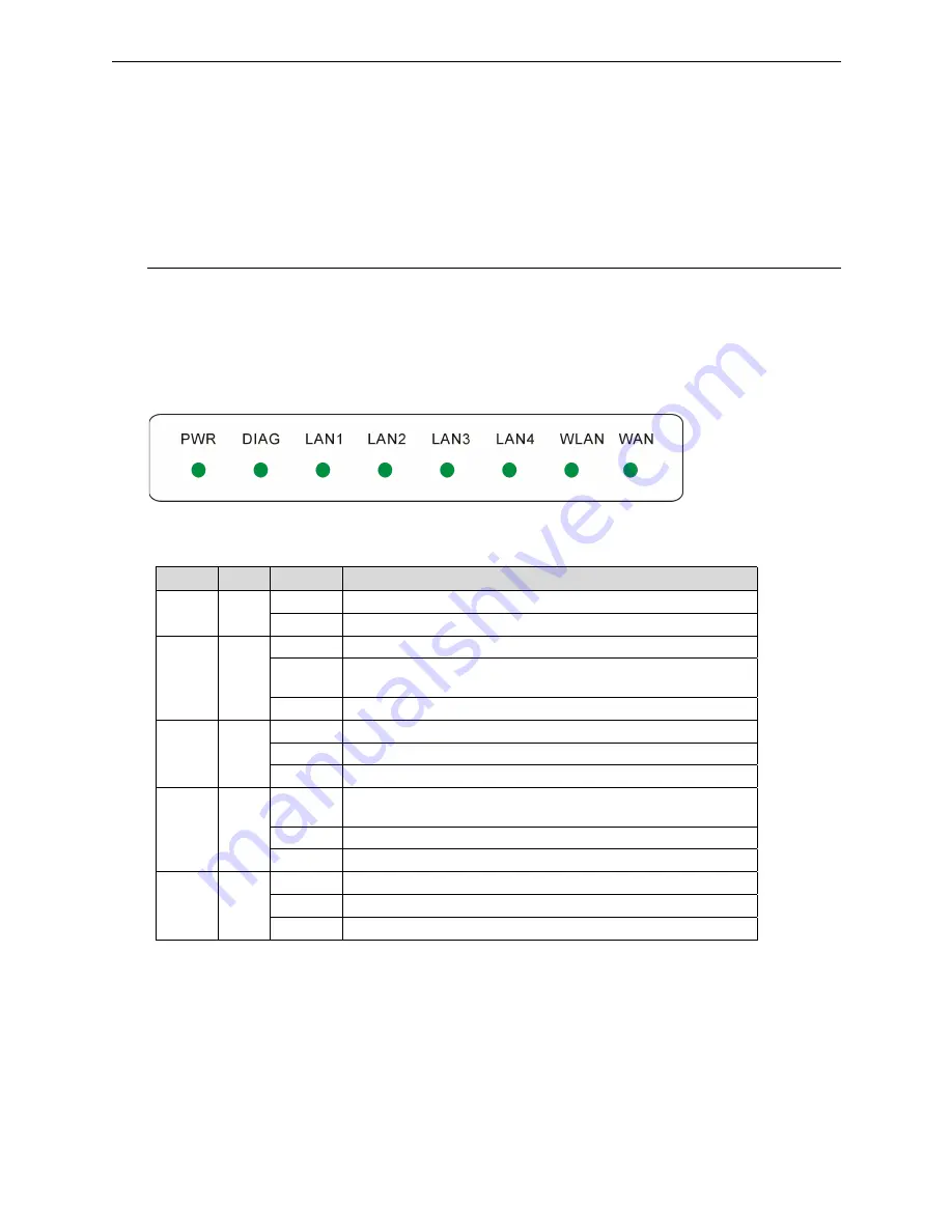
The figure below illustrates the front panel of the Broadband Cable/DSL Wireless Router. It indicates the status of
the router in.
After powering on the router, the PWR LED will be on till powering off. These LEDs will not be on simultaneously.
When this device is transferring data, the LED will be blinking to indicate that which port that you are using.
LED Indicators
The ADSL Router is equipped with eight LEDs on the front panel as described in the table below (from left to right):
LED
Color Status
Description
Unlit Power
off.
PWR Green
Solid Power
on.
Unlit
Power off or initial self-test of the unit is OK.
Blinking
When software downloading or updating operation parameters located in
FLASH memory is in progress.
DIAG Green
Solid
Initial self-test failure or programming FLASH memory failure.
Unlit
Power off or no Ethernet carrier is present.
Blinking
Ethernet carrier is present and user data is going through Ethernet port.
LAN 1 –
LAN 4
Green
Solid
Ethernet carrier is present.
Unlit
Power off or no radio signal (WLAN card is not present or fails to
function).
Blinking
Traffic is going through Wireless LAN interface.
WLAN Green
Solid
Wireless LAN interface ready to work.
Unlit
Power off or line connection is handshaking or training is in progress.
Blinking
User data is going through WAN port.
WAN Green
Solid
Line connection is OK.
Summary of Contents for RTW026
Page 1: ...i Broadband Wireless Router User s Manual Rev 01 2003 04 02...
Page 10: ......
Page 16: ...Wireless Broadband Router User s Manual 6...
Page 72: ...Wireless Broadband Router User s Manual 62...
Page 75: ...Chapter 5 Troubleshooting 65...


