background image

80001028 

– Issue 1 10/21 


5.0 Operation 

Section 5 contains information about the operation of the unit and includes the correct 
operation of the potentiometer, speed control and an explanation of the labels that are 
present on the unit.  


5.1 Operating the Power 

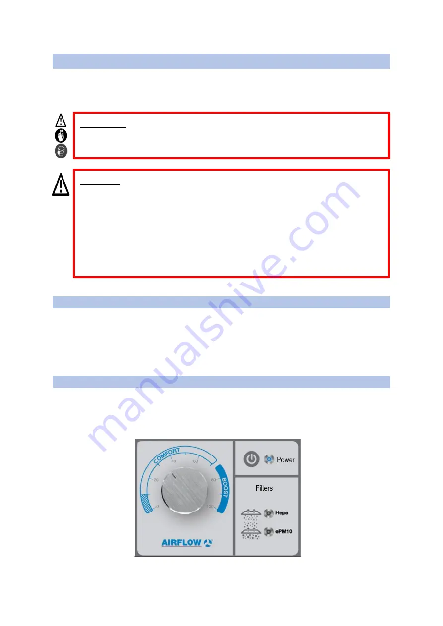
The fan is directly controlled by the speed controller (potentiometer). Push the rotary control 
inwards to power the unit. The blue LED indicates the unit is running. The unit cannot be 
switched on or off by pressing the blue button, it is for indication purposes only, the 
potentiometer must be pressed in to power on the unit. Switch the switch down on the back 
of the unit to engage the plug power supply.  
 

5.2 Speed Control 

Turn the knob of the potentiometer clockwise to increase the speed and the airflow. Turn the 
potentiometer anti-clockwise to decrease it. The adjustment levels with power draw and 
airflow rates can be seen in section 3.0, Table 3 and 4 of this document. Comfort is intended 
to be the everyday operating speeds, and boost for short periods of increased purification. 
 

Danger:


Danger to life due to electric shock. An electric shock can result in 

death or serious injury. The unit must be fully isolated from the mains power 
supply before all maintenance work and before opening the terminal 
compartment!  
 

Do not operate the unit without a proper electrical grounding/earthing. 

Make  sure  the  unit  is  connected  to  a  power  supply  with  a  30  mA 
individual RCD. 

Always disconnect the unit power supply before performing any service 
or maintenance work.  


Warning:


Make sure to use protective gloves and a protective mask (min. 

FFP2) BEFORE performing service and/or maintenance work. 


Figure 1:Speed control potentiometer


Summary of Contents for 90001459

Page 1: ...Installation operation and maintenance manual Part No 90001459 90001460 Purigo M650 M850 Please keep this manual with the product ...

Page 2: ...Filter Disposal 5 2 2 Electrical Connection 5 2 3 Recycling 5 3 0 Technical Information 6 4 0 Installation 8 4 1 Unboxing 8 4 2 Installation Location 8 4 3 Mobility 8 4 4 Electrical Connection 8 5 0 Operation 9 5 1 Operating the Power 9 5 2 Speed Control 9 6 0 Maintenance and Service 10 6 1 Important safety information 10 6 2 Maintenance Schedule 11 6 3 Components 11 6 3 Filters 12 Notes Error Boo...

Page 3: ...small particles dust pollen bacteria and viruses Protective gloves serve to protect the hands against rubbing abrasions cuts or more injuries as well as contact with hot surfaces Protective footwear serves to protect against heavy falling parts and from slipping on slippery surfaces Danger Always pay close attention to danger and warnings signs To not do so could cause serious personal injury deat...

Page 4: ...esigned to be used in a typical residential commercial environment It is for indoor use only and works with 230V AC supply from a normal utility socket It can be used for filtering indoor air by means of recirculating it and removing the small particles dust pollen bacteria and viruses with the help of air filters Any use other than the intended use is prohibited Do not use the unit at a relativel...

Page 5: ...contractor must ensure that the components are separated according to material type 2 1 Filter Disposal The filters of the unit can be considered toxic and harmful to the environment once they are due for replacement Please dispose of these in the most appropriate manner to the local authority 2 2 Electrical Connection The product does not contain batteries in the event of the failure of the unit ...

Page 6: ... consumption W 170 170 Max power consumption A 1 7 1 7 Voltage V 230 50 60 230 50 60 Filters HEPA H14 H14 Filters EPM ePM10 70 ePM10 70 Table 3 Technical Specification Specification M850 M650 Airflow Volume min m3 h 160 100 Airflow Volume max m3 h 850 650 Max covering area m2 71 54 Sound Power Min dBa 34 35 Sound Power Max dBa 66 69 Acoustic Pressure min dBa 1m 26 27 Acoustic Pressure at Max dBa 1...

Page 7: ...54 97 75 700 768 56 125 80 768 815 57 149 85 815 830 57 160 90 830 844 58 168 95 844 844 58 168 100 844 844 58 168 Table 5 M650 Setting levels M650 Adjustment levels Air Volumes m3 h Noise level at 1m dBa Power W 20 0 90 27 4 25 90 140 32 6 30 140 180 37 8 35 180 200 39 12 40 200 270 43 17 45 270 310 46 24 50 310 350 48 32 55 350 400 51 44 60 400 460 53 59 65 460 490 55 74 70 490 535 57 93 75 535 ...

Page 8: ...nce Do not put the unit in a location which will exceed its maximum temperature tolerances Do not place the unit in areas which are to be kept clear for any reason such as a fire exit Allow easy access for adjustment of the potentiometer Do not place the unit inside a cupboard wardrobe or cabinet Do not rest heavy objects on the unit or use it to hold other objects in place It is recommended to no...

Page 9: ...the speed and the airflow Turn the potentiometer anti clockwise to decrease it The adjustment levels with power draw and airflow rates can be seen in section 3 0 Table 3 and 4 of this document Comfort is intended to be the everyday operating speeds and boost for short periods of increased purification Danger Danger to life due to electric shock An electric shock can result in death or serious inju...

Page 10: ...cts the airways from small particles dust pollen bacteria and viruses Protective gloves serve to protect the hands against rubbing abrasions cuts or more injuries as well as contact with hot surfaces Protective footwear serves to protect against heavy falling parts and from slipping on slippery surfaces Danger Danger to life due to electric shock An electric shock can result in death or serious in...

Page 11: ...eck for unacceptable levels of dirt odours and damage Replace the filter X Check the filter change indicator next to adjustment knob Replace the filter X Fan Check for pollution shading and corrosion damage Clean or replace the fan X Check for abrasion or unbalance Change the fan X Check internal fan connection cable Repair or replace X Silencer Check for dirt and damage Clean or change X 6 3 Comp...

Page 12: ...ay not perform as intended Device Filter Classes Filter QTY Filter Dimensions Ref No Purigo M650 Epm10 70 1 305x305x100 90001513 HEPA 14 1 305x305x292 90001514 Purigo M850 Epm10 70 1 305x305x100 90001515 HEPA 14 1 305x305x292 90001516 Replacement filters must be ordered from Airflow Developments To replace the filters follow the step by step guidance below 1 Remove the back cover unscrewing it wit...

Page 13: ...ow Developments Limited Aidelle House Lancaster House Cressex Business Park High Wycombe Buckinghamshire HP12 3QP UK Email info airflow com Telephone 44 0 1494 525252 Facsimile 44 0 1494 461073 Copyright 2016 Airflow Developments Ltd ...

Reviews: