background image

Note: 

The  G4  filters  should  be  replaced  once  every  six  months  or  after  a  maximum  of  two 

cleaning  cycles.  If  an  optional  F7  filter  is  used  please  replace  these  filters  after  every 
maintenance cycle (replacement filters are available on www.airflow.com, see page 15 for part 
numbers).

Step 3: 

Place the filters in the filter slots, close the service cover and slide it to the right to secure.

Approximately  every  two  years  it  is  recommended  that  the  heat  exchanger  is  checked  for 
contamination.  This  time  scale  may  vary  depending  on  the  surroundings  of  the  property. 
Inspection should be carried out when checking the filters.  

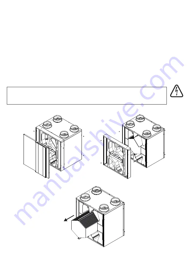
10.2 Heat Exchanger Maintenance

Page

 26 

of

 32

Step 1: 

Remove the front cover plate and the bypass module by unscrewing the screws.

Step 2: 

Remove the filters and pull the heat exchanger out gently using the green strap.

Caution: 

The fins of the heat exchanger are very thin and can easily be damaged.

WARNING

THE FAN AND ANCILLARY CONTROL EQUIPMENT MUST BE ISOLATED 
FROM THE POWER SUPPLY DURING MAINTENANCE.

Danger

Electric Shock

risk

Summary of Contents for 90000660

Page 1: ...MODEL BV400 Mechanical Ventilation with Heat Recovery User and Maintenance Manual Part No 90000660 PLEASE RETAIN THESE INSTRUCTIONS WITH THE PRODUCT Page 1 of 32 ...

Page 2: ...Page 2 of 32 ...

Page 3: ... Screen 9 3 Pro Panel Error Code List 9 4 Modbus Connection 9 5 Fan Speed Adjustment 9 6 Other Control Functions 9 7 Control Card Troubleshoot 10 Maintenance Instructions 10 1 Filter Maintenance 10 2 Heat Exchanger Maintenance 10 3 Sensor Replacing Instruction 10 4 Other Maintenance Procedures 11 Accessories 12 Troubleshooting 13 Declaration Of Conformity 14 Warranty 4 4 5 6 6 7 8 9 10 11 12 14 15...

Page 4: ...sit www airflow com Please keep this manual in a place where it is accessible at all times In case of loss of this document please refer to the relevant product page on our website The manufacturer is not liable for damage caused by unprofessional installation and operation that is not in compliance with this manual Failure to follow these instructions may cause the loss of product warranty Electr...

Page 5: ... time SupplyAir Fresh oxygenated air from outside passes through the filter and heat exchanger before being supplied into bedrooms living and dining rooms etc This fresh air is drawn into the various wet rooms collecting pollutants on its way such as moisture odours allergens and volatile organic components The air is also heated as it passes from room to room using the statutory gap at the bottom...

Page 6: ...Class Operating Temperature Operating Humidity Dimensions W x H x D Weight Low speed air flow is given for 50 Pa 450 m h 125 l s 370 m h 103 l s 90 5 0 259 W m h 230V 1PH 50Hz 169 W 1 5 A G4 F7 optional 160 mm 22 mm IP44 10 C to 40 C 0 to 80 RH 710 x 725 x 630 mm 41 kg 50 m h 3 0 V Low 160 m h 5 5 V Medium 310 m h 8 0 V High 370 m h 10 0 V Boost 4 Components 5 Technical Data Page 6 of 32 1 2 2 3 4...

Page 7: ...Page 7 of 32 0 0 50 100 150 200 250 300 350 400 450 500 100 200 300 400 450 500 350 250 150 50 Air Volume m h External Pressure Pa Low Speed Medium Speed High Speed Boost 6 Performance Curve ...

Page 8: ...pplications according to the table below Noise Rating Curve Maximum Noise Rating Level Application NR 25 Concert halls broadcasting and recording studios churches NR 30 Private dwellings hospitals theaters cinemas conference rooms NR 35 Libraries museums court rooms schools hospitals operating theaters and wards flats hotels executive offices NR 40 Halls corridors cloakrooms restaurants night club...

Page 9: ...Rear Front Front 630 610 A clear space of 600mm should be provided in front of the unit to allow for servicing Page 9 of 32 Clearance for condensate drain Front View Front View Service Space Top View Top View 710 725 731 10 160 287 116 23 130 103 475 Rear Rear Front Front 630 610 All dimensions are in mm min 110 mm ...

Page 10: ...regulations to ensure optimum ventilation of the house Note The low and high speed levels can be adjusted for commissioning purposes by changing values in Registers 68 71 in Pro Panel please see chapter 9 4 4 This can be also done by using manual potentiometers which are located at the control box mounted on the Fan module inside the unit The medium speed has been set in the controller s software ...

Page 11: ...onds When child proof protection is active keypad is locked and buttons do not work To deactivate this function press and for 3 seconds 8 Press and simultaneously to adjust screen brightness and contrast 5 Press to activate boost function for 3 seconds Do not connect any accessorıes or ancillerias such as the pro panel or any additional sensors unless the unit ıs down powered and isolated from the...

Page 12: ...creen 4 Screen Screen Brightness and Contrast Setting Company Introduction Timer Main Screen Standard mode Single fan mode only exhaust fan is running Single fan mode only supply fan is running VOD Auto mode Fan speed High Fan speed Med Fan speed Low Fan speed Boost Fan speed Auto If unit is on VOD mode Fan is off Supply fan Fan is on Exhaust fan airflow com 9 2 Pro Panel Screen ...

Page 13: ... is on at first and second stage There is water coil It is off Cooling coil is on Heating coil is on No failure freezing scenario is off During a failure situation the code ERR and its code will be seen on screen Filter dirty Freezing scenario is on There is no by pass By pass is off By pass is on BMS and TIMER is not adjusted BMS is on TIMER is on 9 2 Pro Panel Screen 9 2 1 Screen Symbols Main Sc...

Page 14: ...s Saturdays TIMER TIMER is on All days Company logo and internet address Pro panel software version 9 2 Pro Panel Screen 9 3 Pro Panel Error Code List Register 25 Value 0 Unit is working normally 1 ERR 1 Fire alarm 2 ERR 2 Heater alarm 3 ERR 3 Supply fan failure OA 4 ERR 4 Exhaust fan failure RA 5 ERR 5 Outdoor air temperature sensor failure OA 6 ERR 6 Return air temperature sensor failure RA 7 ER...

Page 15: ...one Data Bits 8 Stop Bit 1 Communication network is showed below Control board can be connected to RS485 on which is connected more than one unit Address conflicts on this line should be removed and necessary software settings should be done for data communication If the line is too long or if any communication problem occurs 120 Ohm resistance should be added at the beginning and end of the line ...

Page 16: ...ame ID 28 17 Supply fan high speed value Filter Sensor 29 1 r Exhaust fan low speed value 30 54 1 rw 0 2 Supply fan fault method selection 55 1 rw 0 2 Exhaust fan fault method selection 57 1 rw ºC 1 10 2nd stage temperature difference 0 Tachout 1 NC 2 NO 0 Standard 1 Only exhaust fan 2 Only supply fan 3 VOD 0 Tachout 1 NC 2 NO 1 1 r r Shows if the filter sensor is installed or not 1 r Exhaust fan ...

Page 17: ...st fan high speed reference point 1 rw sn 20 600 30 74 75 Thermostat option Thermostat option for room 1 rw 79 1 rw 5 50 Run percentage of frost protection senario in a period 80 1 rw 0 1 Selection of frost protection algoritm 81 1 rw 0 3 Selection of fire senario 0 Troom 1 TerSA 0 TerRA 1 TerP 0 FanOA Low FanRA High 1 FanOA Stop FanRA Run 0 FanOA 1 FanRA 2 FanOA and FanRA 82 1 rw 0 50 0 2 5 60 Fa...

Page 18: ...er limit value of sensor Sensor 2 status 5 0 0 90 91 92 93 96 100 101 113 1 1 1 rw rw rw 1 254 1 254 0 9999 Control board connection address Pro Panel modbus address Service menu password 1 1 1919 0 Passive 1 Active 0 Passive 1 Active r read rw read and write Page 18 of 32 1 Press and simultaneously for 3 seconds to active service menu 2 Press for entering password 4 Press for approval 5 Press for...

Page 19: ...commissioning purposes by changing values in Registers 68 71 in Pro Panel please see chapter 9 4 4 This can be also done by using manual potentiometers which are located at the control box mounted on the Fan module inside the unit The medium speed has been set in the controller s software by the manufacturer and is set as the average value of the manually adjusted low and high speed levels 9 6 Oth...

Page 20: ...emperature the bypass damper will open This will tend to lower the indoor air temperature until it reaches the set temperature level 22 C Volt free connection for boost Switched live connection for boost 2 1 UNIT OK UNIT FAULT UNIT RUN Page 20 of 32 The factory set can be changed on pro panel screen Outdoor air temperature Indoor air temperature Set temperature 1 Press for coming to marked area th...

Page 21: ...inder facility which has been pre set to 4 months When this time interval is reached the red warning light on the control panel flashes for filter maintenance indication After filter cleaning replacing is done filter setting time can be reset by pressing simultaneously hold and during reset time that appears on screen When countdown is over press on Pro Panel Alternatively optional pressure sensor...

Page 22: ...ntrols the hot water coil which helps to increase supply air temperature and works due to set and return air temperature It can control 230V on off valve connected to water coil Note To activate this function following must be applied Turn electric heater function on Turn dip switch 1 on Make short cut in between HT_Fault and HT_P_Fault inputs Connect 230V on off valve to 1 step electric heater co...

Page 23: ... device on the heater the alarm code gives the value 2 In this case the unit continues to operate in fan mode the heaters will not operate If the unit unexpectedly gives this alarm code please check the HT and HT_P sockets Also please check the status if it works or not and the wiring of the safety device on the heaters After the unit is turned on the system continuously checks the tacho informati...

Page 24: ...s operating in VOD Mode the unit will be in OFF mode and the alarm code gives the value 9 If the unit unexpectedly gives this alarm code the wiring to the SENS1 socket needs to be checked If the sensor input is not at the desired value while the unit is operating in VOD Mode the unit will be in OFF mode and the alarm code gives the value 10 If the unit unexpectedly gives this alarm code the wiring...

Page 25: ... of this ventilation system to guarantee years of trouble free operation and ensure that clean air is supplied into your home the filters must be periodically cleaned or replaced depending on contamination of the outdoor air Step 1 Slide the service cover to the left open it and remove the filters Step 2 Use a vacuum cleaner to clean the dust from the air filter If necessary use warm water with de...

Page 26: ...ecommended that the heat exchanger is checked for contamination This time scale may vary depending on the surroundings of the property Inspection should be carried out when checking the filters 10 2 Heat Exchanger Maintenance Page 26 of 32 Step 1 Remove the front cover plate and the bypass module by unscrewing the screws Step 2 Remove the filters and pull the heat exchanger out gently using the gr...

Page 27: ...ation Outdoor air sensor location Vacuum Cleaner Page 27 of 32 10 3 Sensor Replacing Instruction 1 1 2 2 WARNING Step 1 Slide the service cover to the left open it and remove the filters THE FAN AND ANCILLARY CONTROL EQUIPMENT MUST BE ISOLATED FROM THE POWER SUPPLYDURING MAINTENANCE Remove the Filters Open the Service Cover Slide the Service Cover Left Danger Electric Shock risk ...

Page 28: ...ed fromAirflow Developments Ltd Mechanical ventilation units require good quality ducting and a high standard of installation To ensure the best results we recommend the innovative AIRFLEX PRO semi rigid ducting system 10 4 Other Maintenance Procedures 11 Accessories Part Number Product Description G4 filter pack 2 filters F7 filter pack 2 filters Boost switch 1 way Electric duct heater 1 kW can b...

Page 29: ...e trap U bend below the unit is empty The condensate pipe is not completely in the trap The condensate pipe or condensate trap is blocked or frozen Air extract rates are too low The filters are polluted blocked The grilles are dirty Air extract rates are too low Mains voltage failure Check the duct insulation If the heat exchanger is frozen contact your supplier installer to reduce the set point o...

Page 30: ...Page 30 of 32 13 Declaration Of Conformity ...

Page 31: ...Page 31 of 32 ...

Page 32: ...een installed in accordance with latest Building Regulations and IEEE wiring regulations 6 Has been installed by a competent person who is qualified to do so Airflow Developments shall not be liable for any loss injury or other consequential damage in the event of a failure of the equipment or arising from or in connection with the equipment excepting only that nothing in this condition shall be c...

Reviews: