N e utra l W ire F rom
O utle t B ox
(
W hite W ire
)
R e ce ive r
F a n
R ed W ire
with
"A C IN L " s ticke r
R ed W ire
with
"A C IN N " s ticke r
H ot W ire F rom
O utle t B ox
(B la ck W ire )
G round W ire
(
G re e n W ire
)
1
2
3
4
1
2
3
4
1
2
3
4
1
2
3
4
1
2
3
4
1
2
3
4
1
2
3
4
1
2
3
4
1
2
3
4
1
2
3
4
1
2
3
4
1
2
3
4
1
2
3
4
1
2
3
4
1
2
3
4
1
2
3
4
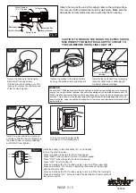
( Fig 2.)
ON DIP
1 2 3 4
Key
"ON" position
"OFF" position
( Fig 1.)
FREQUENCY SETTER
(Ex-Factory Mode)
Before installing Remote Controller, make sure the Main Power
Supply is turned off.
AC:110V~130V/60Hz
LIGHT: 165W (MAX)
FAN: 60W (MAX)
Warning:
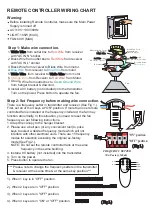
There is a frequency setter in transmitter and receiver (See Fig 1.).
First, set all of the 4 keys at "ON" position. If more than one remote
controlled fan is installed or the frequency interfered, the fan may
function abnormally. In this situation, you need to reset the fan
frequency as per following instructions.
1. Adapt the canopy to the hanger bracket.
2. Please use a ball pen (or any convenient tool) to poke
keys to select a desired frequency mode which will not
interfere with other electrical units. There are 15 frequency
modes for selection excluding the original ex-factory
mode (See Fig 2.).
NOTE: Do not set the remote controlled fans at the same
frequency in the same building.
3. Install a 9V battery (not included) into the transmitter.
4. Turn on the power.
5. Press button to operate the fan.
***
Please note to change the frequency-setters in the transmitter
& receiver at the same time & at the same key position.***
Step 1: Make wire connection.
Step 2: Set Frequency before making wire connection.
1. White Wire from outlet box to
Red Wire
from receiver
with "AC IN N" sticker.
2. Black Wire from outlet box to
Red Wire
from receiver
with "AC IN L" sticker.
3. Black Wire from receiver to Black Wire from motor.
4.
Blue Wire
from receiver to
Blue Wire
from motor.
5. White Wire from receiver to White Wire from motor.
6.
Orange Wire
from Receiver to
Red Wire
from Motor.
7. Ground Wire from outlet box to
Green Ground Wire
from hanger bracket & downrod.
8. Install a 9V battery (not included) into the transmitter.
Turn on the power. Press button to operate the fan.
REMOTE CONTROLLER WIRING CHART
1). When 1 key is in "OFF" position.
2). When 2 keys are in "OFF" position.
3). When 3 keys are in "OFF" position.
4). When 4 keys are in "ON" or "OFF" position.
U / L
D / L
HI
MED
LOW
OFF
R E M O T E
C O N T R O L
U / L
D / L
O F F
H I
M E D
L O W


