


507148-01
Page 5 of 14
Issue 1406
Vertical
Venting
1. Local building codes may have more stringent
installation requirements and should be consulted
before installation of the unit.
2. The flue pipe should be as short as possible to do the job.
3. The flue pipe should not be smaller than the outlet
diameter of the flue outlet of the furnace.
4. Single wall flue pipe should not run outside or through
any unconditioned space.
5. The chimney should terminate 2’ above the highest peak
of a peaked roof, and 3’ higher than a flat roof.
6. The flue pipe must not pass through a floor or ceiling.
Clearances to single wall flue pipe should be no less than
specified in the Clearances section beginning on page 3.
7. The flue pipe may pass through a wall where provisions
have been made for a thimble as specified in the
Standards of the National Board of Fire Underwriters
(see Figure 6).
8. The flue pipe should slope upward toward the chimney
on a horizontal run of at least 1/4” per foot and should
be supported by something other than the furnace (see
Figure 7 on this page and Figure 8 on page 8).
9. Extend the flue pipe into the chimney so that it is flush
with the inside of the flue liner. Seal the joint between
the pipe and the liner.
10. The furnace shall be connected to a factory-built
chimney or vent complying with a recognized standard,
or a masonry or concrete chimney lined with a lining
material acceptable to the authority having jurisdiction.
11. When two or more appliances vent into a common flue,
the area of the common flue should not be less than the
area of the largest flue or vent connection plus 50% of
the areas of the additional vents or flue connections. The
chimney must be able to sufficiently vent all appliances
operating at the same time.
12.
The flue pipe shall not be connected to a chimney
flue serving a solid fuel appliance or any mechanical
draft system.
13. All unused chimney openings should be closed.
14. All vent pipe run through unconditioned areas or outside
shall be constructed of factory-built chimney sections
(see Figure 7).
15. Where condensation of flue gases is apparent, the vent
shall be constructed to prevent the condensation from
entering the flue transition box opening. Provisions shall
be made to drain off the condensate (see Figure 7).
16. Vent connectors serving this appliance shall not be
connected into any portion of a mechanical draft system
operating under positive pressure.
17. Keep the area around the vent terminal free of snow,
ice, and debris.
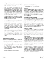
Wall Thimble
Figure 6
Thimble
Flue Pipe
Combustible Wall
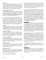
Figure 7
Factory-Built Chimney
Rear Flue
Barometric Control
(in either location)*
Factory-Built
Chimney
Drain for
Condensate
Factory-Built
Chimney
Barometric Control
(in either location)*
Drain for
Condensate
* Barometric control may be installed in either the vertical or
horizontal section of the flue pipe within 18” of the flue outlet of
the furnace.
Front Flue


