Air Torque AT045U Mounting And Operating Instructions Download Page 12

3-2  

EB AT-RP-4GU EN

Design and principle of operation

3.2  Complementary/accessory parts
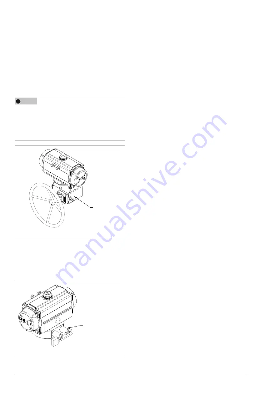
Gearbox

It is an emergency manual override system designed to 
provide manual operation to drive the actuator and the valve 
in the safe position when the supply pressure is not available 
in case of any emergency situation. The actuator and the 
valve are operated rotating a handwheel. (Fig. 3-4)


Î

Refer to the gearbox instruction manual available from 
AIR TORQUE.  

Risk of actuator damage due to incorrect gearbox stroke 
adjustment.


Make sure that the actuator and the gearbox are correctly 
oriented, with reference to the rotation direction required.


Make sure that the stroke of the gearbox does not exceed 
the stroke allowed by the actuator.

Fig. 3-4 

 GEARBOX

Block and safety lock-out system

The block and safety lock-out system permits to lock the actua-
tor and the valve in specific cases, despite the fail action of 
the actuator. (Fig. 3-5)


Î

Refer to technical data T.D.S. 4.3.1.

Fig. 3-5 

BLOCK AND SAFETY
LOCK-OUT SYSTEM

NOTICE

!

3.3  Technical data

The nameplate provides information on the actuator configu-
ration.


Î

Refer to section 2.1 ‘Actuator nameplate sample‘.


Î

More informations are available in the actuator model 
technical data sheet available from AIR TORQUE.

Power operating media


Use dry or lubricated air or inert gas.


Make sure the operating media is compatible with the ac-
tuator internal parts and lubricant.


In case of pressure medium different than Group 2 fluids 
according to the PED 2014/68/EU, contact AIR TOR-
QUE.


The operating media must have a dew point equal to 
–20°C (-4°F) or at least 10°C (18°F) below the ambient 
temperature.


The maximum particle size contained into the operating 
media must not exceed 30 μm.

Supply pressure


The maximum operating pressure is 8 bar (116 Psi).


Î

Refer to section 2.1 ‘Actuator nameplate sample‘ (Table 
2-1, position 05).


For double acting and single acting actuators the working 
pressure is from 2.5 bar (36 Psi) to 8 bar (116 Psi).


Î

Refer to the actuator model technical data for output tor-
que values related to the working pressure range.

Operating temperature

The nameplate provides indication on the operating tempera-
tures.


– “ST” actuators for standard temperatures from  

-40°C (-40°F) to +80°C (+176°F).


– “HT” actuators for high temperatures from  

-15°C (+5°F) to +150°C (+302°F).


– “LLT2” actuators for extremely low temperatures from 

-60°C (-76°F) to +80°C (+176°F).


Î

Refer to the data sheet RP10600E for the soft spare parts 
material and lubricant type in relation to the different wor-
king temperature ranges.

Stroking time

The stroking time depends on several factors such as supply 
pressure, supply system capacity (tubing diameter, pneumatic 
accessories flow capacity), valve type, valve torque, applied 
safety factor, cycle frequency, temperatures, etc. Nevertheless, 
an indication of the stroking time in clearly defined conditions 
is available in the actuator model technical data sheet.

Summary of Contents for AT045U

Page 1: ...Original instructions EB AT RP 4GU EN 4th Generation Upgrade Series Rack Pinion actuators AT045U AT801U models Edition November 2020...

Page 2: ...If you have any questions about these instructions con tact AIR TORQUE s After sales Service Department info airtorque de The mounting and operating instructions for the devices are included in the s...

Page 3: ...e actuator 4 1 4 3 Transporting and lifting the actuator 4 1 4 3 1 Transporting the actuator 4 1 4 3 2 Lifting the actuator 4 1 4 4 Storing the actuator 4 2 5 Mounting and assembly 5 1 5 1 Preparation...

Page 4: ...4 EB AT RP 4GU EN...

Page 5: ...tive equipment Revisions and other modifications Revisions conversions or other modifications of the product are not authorized by AIR TORQUE They are performed at the user s own risk and may lead to...

Page 6: ...ains moving parts which can injure hands or fingers Do not touch or insert hands or finger into moving parts Before starting any work on the actuator disconnect all pneumatic hydraulic electrical supp...

Page 7: ...tening torques lead to parts wearing out quicker Parts that are not tightened enough may loosen Refer to section 15 2 Tightening torques Risk of actuator damage due to the use of unsuitable lubri cant...

Page 8: ...1 4 EB AT RP 4GU EN Safety instructions and measures...

Page 9: ...ut torque at specified supply pressure for Double acting Max output torque Nominal torque at 5 5 bar Nominal pressure for Single acting Max output torque Air Start output torque at specified supply pr...

Page 10: ...2 2 EB AT RP 4GU EN Markings on the device...

Page 11: ...ion Fig 3 2 2 4 2 4 A B The actuators can be controlled by different options direct mounting of control devices for example a solenoid valve or a manifold with NAMUR interface threaded connections to...

Page 12: ...a is compatible with the ac tuator internal parts and lubricant In case of pressure medium different than Group 2 fluids according to the PED 2014 68 EU contact AIR TOR QUE The operating media must ha...

Page 13: ...ifting equipment and accessories who se maximum lifting capacity is higher than the actuator weight including the packaging if applicable Risk of actuator damage due to incorrectly attached slings Onl...

Page 14: ...t AIR TORQUE in case of different storage conditions or long storage periods It is recommended to regularly check the actuator and the pre vailing storage conditions during long storage times Storage...

Page 15: ...ous injury or even death Before starting any work on the actuator disconnect all pneumatic hydraulic electrical supplies and discharge the pressure from the actuator Crush hazard arising from moving p...

Page 16: ...n and operation protect and close the air connections which may not being used immediately Make sure that the operating pressure media composition used for the actuator operation meets the operating c...

Page 17: ...g equipment until the connection bolts are completely tightened Make sure to align correctly the dowel pins or the spigot if any 9 Align the valve stem coupling to the actuator s bore 10 Carefully low...

Page 18: ...5 4 EB AT RP 4GU EN Mounting and assembly...

Page 19: ...near the actuator WARNING Risk of personal injury through incorrect operation use or installation as a result of information on the actuator being illegible Over time markings labels and nameplates o...

Page 20: ...6 2 EB AT RP 4GU EN Start up...

Page 21: ...or installation as a result of information on the actuator being illegible Over time markings labels and nameplates on the actuator may become covered with dirt or become illegible in some other way...

Page 22: ...7 2 EB AT RP 4GU EN Operation...

Page 23: ...e the actuator inspect and remove any foreign object Incorrect assembly after maintenance Disasseble and reassemble the actuator correctly Control system Make sure the control system components are co...

Page 24: ...8 2 EB AT RP 4GU EN Malfunctions...

Page 25: ...ch com ply with the original specifications DANGER WARNING WARNING NOTICE Note With the information given below AIR TORQUE provides the end user with all the required information necessary for ser vic...

Page 26: ...R 13 Fig 9 1 04R 03R 11R 221G 222G 19 2 Table 9 2 PART N 1 UNIT Q TY NOTE DESCRIPTION 01 1 N A for AT045U OCTI CAM Stop arrangement 02 2 N A for AT045U STOP CAP SCREW 03 2 N A for AT045U WASHER 03R 2...

Page 27: ...or AT045U AT101U 19 0 1 GRADUATED RING 19 1 1 N A for AT045U AT101U POSITION INDICATOR 19 2 3 1 MULTIFUNCTION POSITION INDICATOR 19 5 1 N A for AT045U AT101U TOP ADAPTER Drive shaft 19 6 2 N A for AT0...

Page 28: ...efer to Fig 9 1 and Fig 9 3 Remove both stop cap screws 02 together with nuts 04 and washers 03 Remove the stop caps o rings 11 In case of actuator with extra travel stop adjustment Fig 9 3 loosen the...

Page 29: ...me as per the sequen ce shown in Fig 9 5 for the number of turns indicated in Table 9 2 Risk of personal injury due to compressed springs End caps are under tension when the springs are compressed If...

Page 30: ...tially out of the bottom of the body and remove the internal thrust bearing 08 and the oc ti cam 01 Push the drive shaft 60 completely out of the body If needed gently tap the top of the drive shaft 6...

Page 31: ...ip Replace the spring clip 18 if it has been overstressed and loosened In case of spiral spring clip 18 refer to the disassembly and reassembly instructions available from AIR TORQUE Place the spring...

Page 32: ...el stop adjustment fasten the stop screws 221G 222G into the end caps 30 aligning the head of the screw to the end cap sur face as shown in Fig 9 16 lubricate and place the o rings 11R place the washe...

Page 33: ...AT101U to AT801U Fig 9 19 Side A Side A Side B Side B models AT101U to AT801U Place the end cap 30 30R Fix the end cap 30 30R fastening partially the cap screws 13 1 turn at a time following the seque...

Page 34: ...op cap screws 02 into the body 50 Fig 9 24 50 LEFT RIGHT 02 04 03 11 9 5 6 Stroke adjustment Refer to Fig 9 1 and Fig 9 24 Close position With the actuator in close position 0 position referring to Fi...

Page 35: ...e left stop screw 02 1 turn at a time until the desired stop position is achieved Holding the stop screw 02 in position tighten the stop adjustment nut 04 to lock the stop screw 02 Refer to the sectio...

Page 36: ...xhausted during operation Wear eye and hearing protection when working near the actuator Crush hazard arising from moving parts The actuator and the valve assembly contains moving parts which can inju...

Page 37: ...10 2 EB AT RP 4GU EN Decomissioning...

Page 38: ...Wear eye and hearing protection when working near the actuator Risk of personal injury due to preloaded and compressed springs End caps are under tension due to compressed springs Furthermore incorrec...

Page 39: ...ed 2 Disconnect all electrical wirings of the control or signal de vices if any Refer to the control or signal devices documentation for safe disassembly 3 Remove the bolts and nuts from the valve fla...

Page 40: ...ding to how it was originally sized or does not function at all it is defective and must be repaired or replaced Risk of actuator damage due to incorrect repair work Do not perform any repair work on...

Page 41: ...12 2 EB AT RP 4GU EN Repairs...

Page 42: ...compressed springs End caps are under tension due to compressed springs Furthermore incorrect spring cartidges disassembly could re sult in serious injury Before starting any work on the actuator dis...

Page 43: ...13 2 EB AT RP 4GU EN Disposal...

Page 44: ...lowing certificates and documents are available from AIR TORQUE EU Declaration of Conformity page 14 2 ATEX Directive 2014 34 EU SIL Certificate Machine Directive 2006 42 EC DNV Type Approval IP67 and...

Page 45: ...14 2 EB AT RP 4GU EN...

Page 46: ...IVER 15 1 2 Tools dimensions Stop screws 02 and nuts 04 end cap screws 13 Ch 1 Ch 2 Fig 15 2 ACTUATOR MODEL Ch 1 mm Ch 2 mm AT045U 8 AT051U 10 8 AT101U 10 10 AT201U 13 10 AT251U 13 10 AT301U 17 13 AT3...

Page 47: ...nt Fig 15 3 ACTUATOR MODEL 221G 222G 04R TYPE Ch 3 mm Ch 4 mm AT051U A 3 8 AT101U 10 AT201U 4 10 AT251U 10 AT301U 5 13 AT351U B 8 13 AT401U 17 AT451U 10 17 AT501U 19 AT551U 19 AT601U 13 22 AT651U 24 A...

Page 48: ...4 96 102 AT751U M16 150 160 AT801U Table 15 3 Stop screws nuts 04 ACTUATOR MODEL THREAD TIGHTENING TORQUE Nm AT051U M6 8 9 AT101U AT201U M8 18 20 AT251U AT301U M10 34 36 AT351U M12 60 64 AT401U AT451U...

Page 49: ...1 AA 2 AA 3 AA 4 AA 5 M6 8 9 NOTE 1 Refer to section 2 1 Actuator nameplate sample 15 3 Lubricants The 4th GU actuators are factory lubricated for the life of the actuator in normal working condition...

Page 50: ...EB AT RP 4GU EN 15 5 Annex...

Page 51: ...15 6 EB AT RP 4GU EN...

Page 52: ...EB AT RP 4GU EN 15 7...

Page 53: ...2020 11 02 English EB AT RP 4GU EN Air Torque GmbH Im Katzentach 16 18 DE 76275 Ettlingen Tel 49 0 7243 5934 0 Fax 49 0 7243 5934 34 info airtorque de www airtorque de...

Reviews: